Repair Manual For New Holland E50. Illustrations, instructions, diagrams for step by step remove and install, assembly and disassembly, service, inspection, repair, troubleshooting, tune-up.
Format: PDF
Language: English
Pages: 764
Bookmarks: Yes
Searchable: Yes
Number: 87360588
Wiring Diagrams: Yes
Hydraulic Diagrams: Yes
Model
New Holland E50
Contents
- – Table Of Contents
- – Standard Specifications And Maintenance
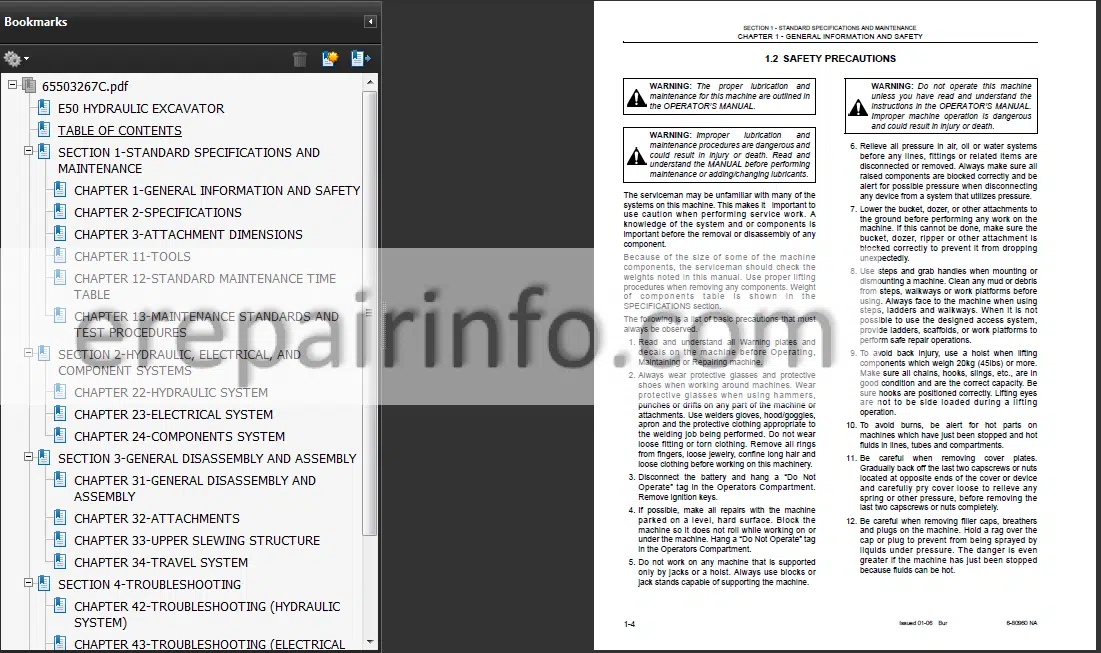
General Information And Safety
Preparation Before Disassembling
Safety In Disassembling And Assembling
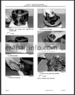
Disassembling And Assembling Hydraulic Equipment
Electrical Equipment
Hydraulic Parts
Welding Repair
Environmental Protection
Specifications And Performance
Speed And Gradeability
Engine
Hydraulic Components
Side Digging & Dozer
Weight
Loading Machine On A Trailer
Transportation Dimension And Weight Of Attachment
Boom With Arm Cylinder
Arm And Bucket (Standard Bucket)
Arm
Bucket (Standard Bucket)
Dozer (Without Cylinder Weight)
Boom Dimensional Drawings
Boom Maintenance Standards
Clearance Of Pin And Bushing On Boom Section
Clearance In Thrust Direction On Boom And Cylinder Installation Section
Arm
Bucket
Dozer
Swing
Torque Specifications For Capscrews And Nuts
Metric Coarse Thread Standard Tightening Torque Values
Metric Fine Thread Standard Tightening Torque Values
Screw And Tool Sizes
Capscrew
Torque Specifications For Joints And Hoses
Joints For Piping (ORing Sealing Type)
Hydraulic Hose ( Degree Flare Type)
Torque Specifications For Sleeve Type Tube Fittings
Sleeve Type Tube Fittings
Part Number
Plugs
Plug For Hydraulic Pipe Joint
Cap Nut (Joint Plug)
Plug (Tube Plug)
Nut
Plug For Hydraulic Equipment
Pf Screw
Pt Screw
Plug For Flare Hose
Working Conditions
Applicable Range Of Standard Maintenance Time
Excluded Time
Applicable Machine For Estimation Of Standard Maintenance Time
Standard Maintenance Time Table
Classification Of Work Code
Time Tables
Attachment
Canopy And Guard
Upper Structure
Under Carriage
How To Use Maintenance Standards And Precautions
Terminology
Precautions For Judgment
Other Precautions
Performance Inspection Standard Tables
Measuring Engine Speed
Engine Speed Measurement
Measuring Hydraulic Oil Pressure
Standard For Hydraulic Oil Pressure Measurement
Pressure Measurement And Adjustment
Main Circuit Pressure
Pilot Circuit Pressure
Measuring Travel Performances
Test Procedure
Travel
Travel Deviation
Movement Drift Due To Gravity
Drain Rate On Travel Motor
Measuring Slew Performances
Test Procedure
Slew Time
Overrun When Slewing Stops
Slew Drift Due To Gravity
Drain Rate Of Slew Motor
Measuring Attachment Operating Performances
Test Procedure
Cylinder Speed
Gravity Drift Of Cylinders
Measuring Slew Bearing Performances
Test Procedure
Slew BearingBucket Tip Play
Slew Bearing Play
Measuring Track Tension
Track Tension
Specifications
Attachment Dimensions
Tools
Standard Maintenance Time Table
Maintenance Standards And Test Procedures - – Hydraulic, Electrical, And Component Systems
Summary
Hydraulic Circuits And Component Models
Hydraulic Circuit Operation
Electrical System
How To Read Circuit Diagram And Harness Connection
Electrical Equipment And Harness
Components System
Hydraulic Components
Electrical Equipment
Function And Features Of Hydraulic Circuit
Hydraulic Circuits And Component Models
Standard Specifications
Hydraulic Circuit Operation
Color Coding Standard For Hydraulic
Neutral Circuit
Travel Operating Circuit
Nd Speed Operating Circuit (IndependentForward Travel)
Slew Operating Circuit
Slew (Left) Operating Circuit
Bucket Operating Circuit
Bucket Digging Operation Circuit
Bucket Dumping Operating Circuit
Boom Operating Circuit
Boom Raise Operating Circuit
Boom Lower Operating Circuit
Arm Operating Circuit
Arm In Operating Circuit
Operating Circuit For Arm Out
Swing Operating Circuit
Swing (Left) Operating Circuit
Dozer Operating Circuit
Dozer Down Operating Circuit
Nibbler & Breaker Operating Circuit
Nibbler Close Operating Circuit
Nibbler Open Operating Circuit
Breaker Blow Operating Circuit
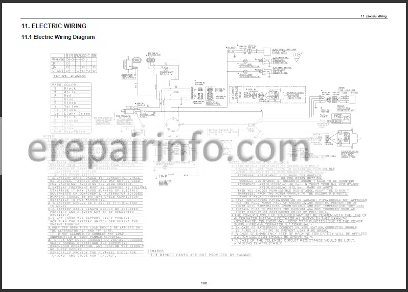
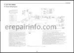
Electric Circuit Diagram
Harness Connection
Electrical Equipment And Harness
Electrical Equipment List
Harness & Cable List
Arrangement Drawing For Components & Harness
Upper Frame Portion
Engine Portion
Relay Unit Portion
Fuel Tank Portion
Work Light Portion
Cab Portion (Opt)
Air Filter Portion (Restriction Switch)
Detail Of Harness & Cable
Inst Main Harness
Engine Harness
Starter Cable
Battery Ground Cable
Engine Ground Cable
Boom Harness
Key Switch Harness
Canopy Working Light Harness
Boom Work Light Extension Harness
Connection Harness With Cab
Air Filter Harness
Hand Control And Slew/Swing Harness
Horn Switch Harness
Instrument Panel Harness (Left)
Hydraulic Components
Electrical Equipment
Hydraulic System
Electrical System
Components System - – General Disassembly And Assembly
General Disassembly And Assembly
Attachments
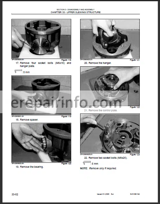
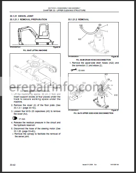
Upper Slewing Structure
Travel System
Removing And Installing
Attachment Assembly And Name
Bucket
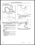
Removal Of Bucket
Installation Of Bucket
Arm
Removal Of Arm
Installation Of Arm
Boom
Removal Of Boom
Installation Of Boom
Swing
Preparation For Removal
Removal Of Swing Bracket And Cylinder
Installation Of Swing Bracket And Cylinder
Dozer
Removal
Installation
Disassembling And Assembling
Cylinder
Necessary Tools
General Precautions
Cylinder Construction (Example Of Boom Cylinder)
Maintenance Standards
Jig List
Possible Causes For Trouble And Remedy - – Troubleshooting
Attachment Operational Failure (Excluding Swing Operations)
Attachment Speed Is Slow
Attachment Operating Power Is Low
Malfunction Of Attachment
Travel Operation
Travel Operational Failure
Travel Speed Is Slow
Travel Power Is Low
It Deviates In Travel Independent Operation
Slewing Operation
Slewing Operational Failure
Slewing Speed Is Slow
Slewing Power Is Low
Malfunction Of Slewing Operation
Pump
Engine Speed Is Reduced Due To Pump Load
Malfunction Of Pump
General
Engine Does Not Start
Horn Does Not Work
Working Lights Do Not Work
Hourmeter Does Not Work
Fuel Gauge Does Not Work
Water Temperature Gauge Does Not Work
Attachment Operation
All Controls Do Not Function
Travel Operation
Travel&Speed Change Does Not Work
Deceleration
Optional Decel Motor Does Not Work
Starting Trouble
Starter Does Not Rotate
Starter Rotates But Hard To Start
Engine Runs Rough
Output Power Low
Engine Low Power
Knocking At High Temperature
Other Trouble
Exhaust Trouble
Excessive Oil Consumption
Excessive Fuel Consumption
Engine Does Not Stop When Ignition Switch Is Turned Off - – Engine
What you get
You will receive PDF file with high-quality manual on your email immediately after the payment.

Reviews
There are no reviews yet