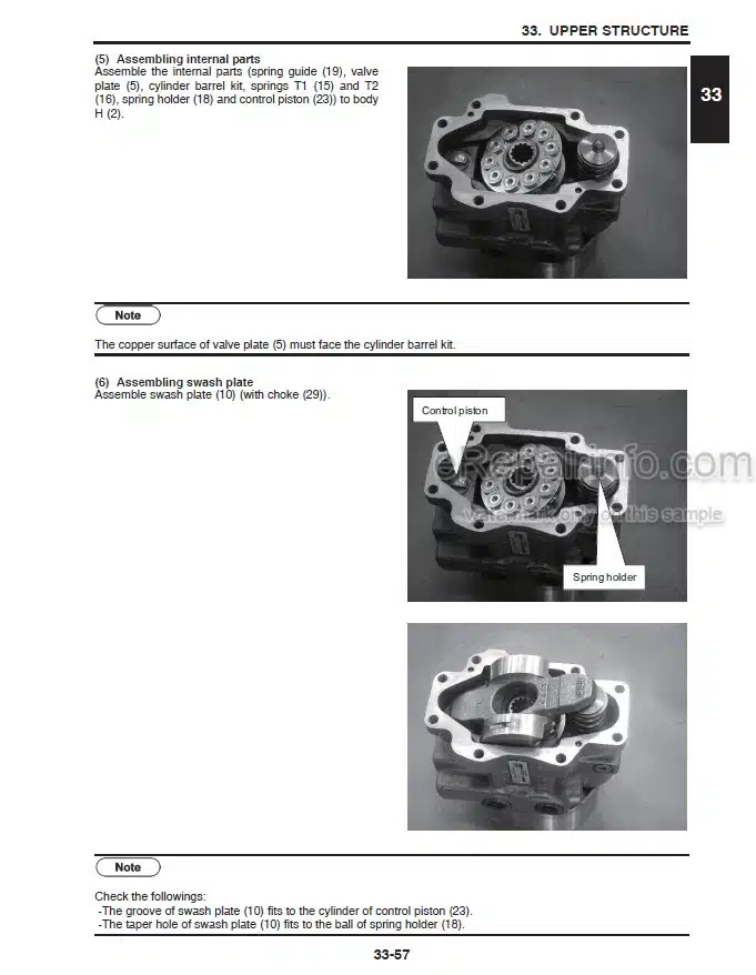
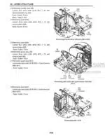
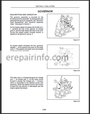
Factory Service Manual For New Holland E55BX Compact Hydraulic Excavator; Yanmar 3TNV88C, 3TNV86CT, 4TNV88C, 4TNV86CT, 4TNV98C, 4TNV98CT Industrial Engine. Manual Contains Illustrations, Instructions, Diagrams For Step By Step Remove And Install, Assembly And Disassembly, Service, Inspection, Repair, Troubleshooting, Tune-Ups.
Format: PDF
Language: English
Pages: 1337
Number: S5HS0013E01 (april 2014)
Bookmarks: Yes
Searchable: Yes
Wiring Diagrams: Yes
Hydraulic Diagrams: Yes
Model
New Holland Compact Hydraulic EXcavator
E55BX
Tier 4
PIN NETN55001 – PS04-10001 and above
Yanmar Industrial Engines
3TNV88C
3TNV86CT
4TNV88C
4TNV86CT
4TNV98C
4TNV98CT
Contents
1.NEW HOLLAND E55BX SERVICE MANUAL COMPACT HYDRAULIC EXCAVATOR.
2.YANMAR TROUBLESHOOTING MANUAL-INDUSTRIAL ENGINES TNV SERIES.
3.YANMAR 3TNV88C, 3TNV86CT, 4TNV88C, 4TNV86CT, 4TNV98C, 4TNV98CT SERVICE MANUAL INDUSTRIAL ENGINES.
1.NEW HOLLAND E55BX SERVICE MANUAL COMPACT HYDRAULIC EXCAVATOR.
-OUTLINE
General Precautions For Repairs
International Unit Conversion System
-SPECIFICATIONS
Components Name
Machine Dimensions
Specifications And Performance
Machine & Components Mass (Dry)
Transportation
Type Of Crawler Shoes
Type Of Bucket
Engine Specifications
-ATTACHMENT DIMENSIONS
Boom
Arm
Bucket
Dozer
Boom Swing
-TOOLS
Torque Specifications For Capscrews & Nuts
Screw And Tool Sizes
Torque Specifications For Joints And Hoses
Torque Specifications For Sleeve Type Tube Fittings
Plugs
Special Spanners For Tubes
Special Tools
Application Of Screw Locking And Sealing Compounds
Counter Weightlifting Jig
Upper Frame Lifting Jig
-STANDARD MAINTENANCE TIME SCHEDULE
Standard Working Time Table For The Maintenance Of Excavator
-MAINTENANCE STANDARD AND TEST PROCEDURE
How To Use Maintenance Standards And Precautions
Performance Inspection Standard Table
Measuring Engine Speed
Measuring Hydraulic Oil Pressure
Measuring Travel Performances
Measuring Swing Performances
Measuring Attachment Operating Performances
Measuring Swing Bearing Performances
Measuring Crawler Tension
DPF (Diesel Particulate Filter)
-MECHATRO CONTROLLER (OPT.)
Mechatro Controller
-HYDRAULIC SYSTEM
General
Hydraulic Circuit And Device Model Numbers
Function Of Hydraulic Circuit
-ELECTRICAL SYSTEM
Electric Circuit Diagram
Electrical Equipment & Harness
Harness
-COMPONENTS SYSTEM
Hydraulic Equipment
Electrical Equipment
-AIR-CONDITIONER SYSTEM
Basic System Of Air, Heater And Cooler
Component Parts And Structure
General Assembly Of Air Conditioner
Structure And Operation Of Major Parts
Removal/Installation Of Blower Motor And Resistor
Disassembly/Assembly Of Air Conditioning Unit
Electric Circuit
Troubleshooting
-GENERAL DISASSEMBLY AND ASSEMBLY
General Disassembly And Assembly
-ATTACHMENT
Removal/Installation Of Assy
Disassembling And Assembling
-UPPER STRUCTURE
Removal/Installation Of Assy
Disassembling And Assembling Of Devices
-TRAVEL SYSTEM
Removal/Installation Of Assy
Disassembling And Assembling
-TROUBLESHOOTING (HYDRAULIC SYSTEM)
General Precautions
Trouble Diagnosis : Hydraulic
Troubleshooting
-TROUBLESHOOTING (ELECTRICAL SYSTEM)
Trouble Diagnosis : Electric System
Troubleshooting
-TROUBLESHOOTING (ENGINE)
-TROUBLE SHOOTING (OPT.) (BY ERROR CODES)
Checking The Site And Actual Thing
Failure Classification And Troubleshooting Procedures
Blown Fuse Of Mechatro Controller
Troubleshooting By Error Codes
2.YANMAR TROUBLESHOOTING MANUAL-INDUSTRIAL ENGINES TNV SERIES.
-DTC (DIAGNOSTIC TROUBLE CODES) GENERAL DESCRIPTION
DTC Code List
Description
Sensor Related
Contact Output Related
CRS (Common Rail System) Related
Actuator
Communication Related
ECU Related
Contact Input Related
Post Treatment Control
Others
-METHOD AND PROCEDURE OF FAILURE DIAGNOSIS
Description
Sensor Related
Contact Output Related
Contact Input Related
CRS (Common Rail System) Related
Actuator
Communication Related
ECU Related
Others
3.YANMAR 3TNV88C, 3TNV86CT, 4TNV88C, 4TNV86CT, 4TNV98C, 4TNV98CT SERVICE MANUAL INDUSTRIAL ENGINES.
-INTRODUCTION
-YANMAR WARRANTIES
YANMAR Limited Warranty
Emission System Warranty
YANMAR Co., Ltd Limited Emission Control System Warranty – USA Only
-SAFETY
Safety Statements
Safety Precautions
-GENERAL SERVICE INFORMATION
Component Identification
Location of Labels
Emission Control Regulations
Emission Control Labels
Engine Family
Function of Major Engine Components
Main Electronic Control Components and Features
Function of Cooling System Components
Installation Position of Sensors
Diesel Fuel
Engine Oil
Engine Coolant
Specifications
Principal Engine Specifications
Engine Service Standards
Tightening Torques for Standard Bolts and Nuts Abbreviations and Symbols
Unit Conversions
-PERIODIC MAINTENANCE
Before You Begin Servicing
Introduction
Periodic Maintenance Schedule
Periodic Maintenance Procedures
-ENGINE
Before You Begin Servicing
introduction
Cylinder Head Specifications
Camshaft and Timing Gear Train Specifications
Crankshaft and Piston Specifications
Cylinder Block Specifications
Special Torque Chart
Special Service Tools
Measuring Instruments
Cylinder Head
-FUEL SYSTEM
Before You Begin Servicing
System Structure
Fuel System Specifications
Fuel System Diagram
Fuel System Components
-COOLING SYSTEM
Before You Begin Servicing
Introduction
Cooling System Diagram
Engine Coolant Pump Components
Engine Coolant System Check
Engine Coolant Pump
-LUBRICATION SYSTEM
Before You Begin Servicing introduction
Oil Pump Service Information Lubrication System Diagram
Checking Engine Oil Pressure
Oil Pump Components
-TURBOCHARGER
Before You Begin Servicing
Introduction
Specifications
Troubleshooting
Turbocharger Components
Turbocharger Component Functions
Washing Procedure
Periodic Inspection
-STARTER MOTOR
Before You Begin Servicing
Introduction
Starter Motor Information
Starter Motor Specifications
Starter Motor Troubleshooting
Starter Motor Components
Starter Motor
-ALTERNATOR
Before You Begin Servicing
Introduction
Dynamo and Alternator Information
Alternator Specifications
Dynamo Specifications
Alternator Troubleshooting
Alternator Components
Alternator Wiring Diagram
Alternator Standard Output
Alternator
Dynamo Component Location
Dynamo Wiring Diagram
Operation of Dynamo
Dynamo Standard Output
Testing of Dynamo
Dynamo
-ELECTRONIC CONTROL SYSTEM
Before You Begin Servicing
Introduction
Electronic Control System
Diesel Particulate Filter (DPF)
Electronic Control Harness Connections
-ELECTRIC WIRING
Electric Wiring Precautions
Electrical Wire Resistance
Battery Cable Resistance
Electrical Wire Sizes – Voltage Drop
Conversion of AWG to European Standards
-FAILURE DIAGNOSIS
Special Service Tools
Tier 4 (BOSCH) Compression Inspection Procedures
Measured Value and Troubleshooting
Quick Reference Table for Troubleshooting
What you get
You will receive PDF file with high-quality manual on your email immediately after the payment.



Reviews
There are no reviews yet