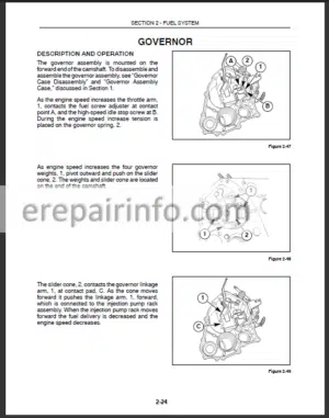
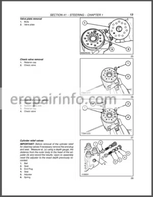
Factory Service Shop Manual For New Holland E70 Hydraulic Excavators. Tons of illustrations, instructions, diagrams for step by step remove and install, assembly and disassembly, service, inspection, repair, troubleshooting, tune-ups.
Format: PDF
Language: English
Pages: 1050
Bookmarks: Yes
Searchable: Yes
Number: 87360603
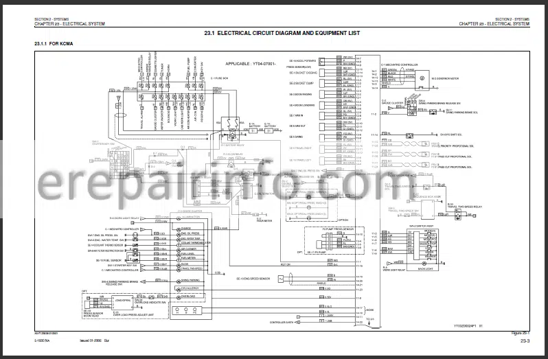
Wiring Diagrams: Yes
Hydraulic Diagrams: Yes
Model
New Holland E70
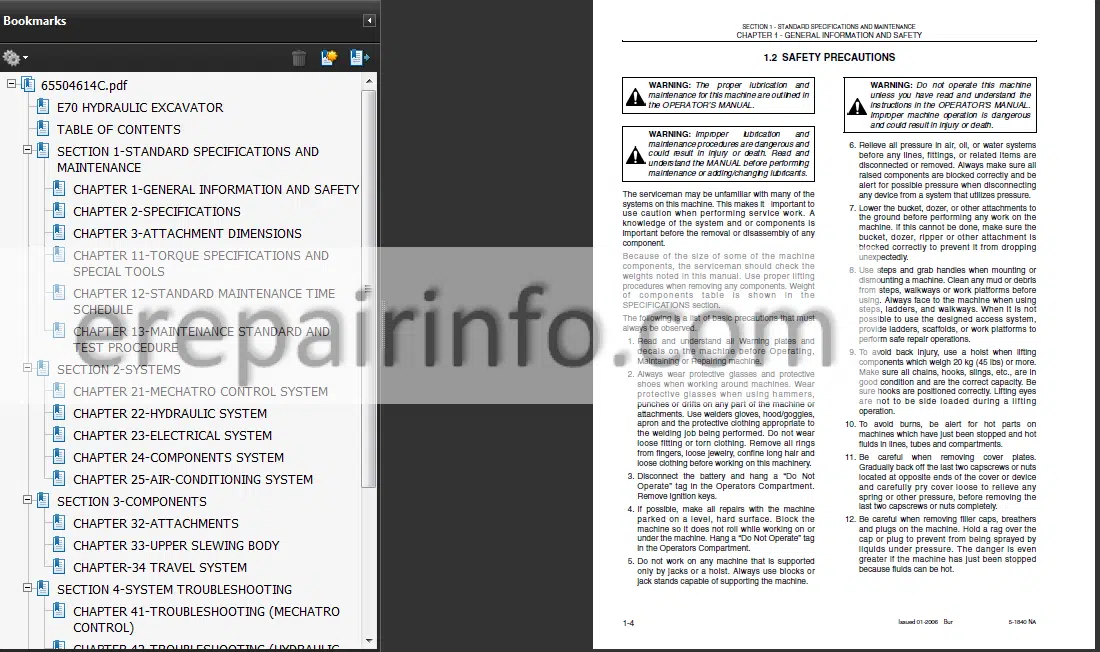
Contents
- – Standard Specifications And Maintenance
–General Information And Safety
General Safety Information
Safety Precautions
General Precautions For Repairs
International Unit Conversion System
–Specifications
Components
Machine Dimensions
Weight Of Components
Transportation Dimension And Weight
Specifications And Performance
Type Of Crawler
Buckets
Attachment Combinations
Engine Specification
–Attachment Dimensions
Boom
Arm
Bucket
Dozer
–Torque Specifications And Special Tools
Torque Specifications For Capscrews And Nuts
Screw And Tool Sizes
Torque Specifications For Joints And Hoses
Torque Specifications For Sleeve Type Tube Fittings
Plugs
Special Spanners
Special Tools
Screw Locking And Sealing Compounds
Suction Stopper
Counterweight Lifting Jig
Boom Foot Pin Pulling Tools
Trunnion Cylinder Pin Pulling Tools
Upper Frame Lifting Jig
Engine Mounting Pedestal
Track Spring Set Jig
–Standard Maintenance Time Schedule
Preface
Standard Maintenance Time Schedule For Excavator
Standard Working Time Table For The Maintenance Of Engine
— Maintenance Standard And Test Procedure
How To Use Maintenance Standard And Precautions
Performance Inspection Standard Table
Measurement Of Engine Speed
Measurement Of Hydraulic Pressure
Measuring Travel Performances
Measuring Swing Performances
Measuring Attachment Operating Performances
Measuring Performances Of Swing Bearing
Mechatro Controller “A” Adjustment - – Systems
— Mechatro Control System
Preface
Mechatro Control System
Boom Raise Conflux Mechatro Control System
Swing Cut Valve Control Mechatro Control System
Arm In / Out Conflux Mechatro Control System
Travel Straight Mechatro Control System
Mechatro Control
— Hydraulic System
Summary
Hydraulic Circuits And Component Models
Hydraulic Circuit Operation
How To Read Circuit Diagram And Harness Connections
Connection And Connector TablesIv
Boom Work LightIx
Key Switch Harness X
Battery And Ground CablesXi
— Electrical System
Electrical Circuit Diagram And Equipment List
Harness
— Components System
Hydraulic Components
Electric Equipment
— AirConditioning System
Construction And Piping
Construction Of Main Components
Function
Disassembly And Assembly
Charging Refrigerant
Electric Circuit
Troubleshooting - – Components
— Attachments
Preface
Removing And Installing
Disassembling And Assembling
— Upper Slewing Body
Preface
Removing And Installing
Disassembling And Assembling
— Travel System
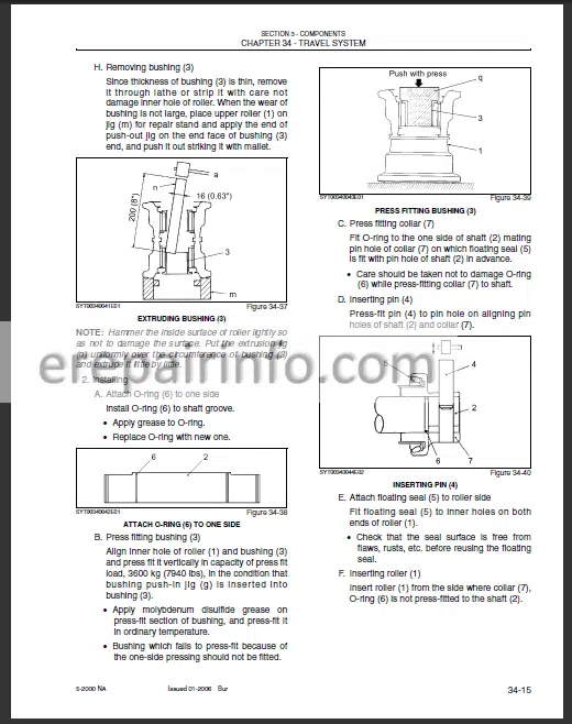
Preface
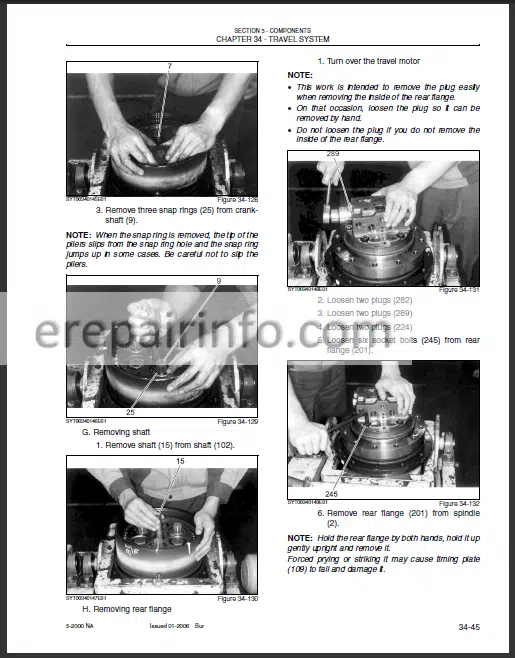
Removing And Installing
Disassembling And Assembling - – System Troubleshooting
— Troubleshooting (Mechatro Control)
Outline
Table Of Actuator For Troubleshooting: Mechatro Control
Troubleshooting Summarized: Mechatro Control
Check Point For Mechatro System
— Troubleshooting (Hydraulic System)
Trouble Diagnosis: Hydraulic
Troubleshooting
— Troubleshooting (Electric)
Trouble Diagnosis Table: Electric
Controller Error Code Display
Service Diagnosis
— Troubleshooting (Engine)
Trouble Diagnosis: Engine
Troubleshooting
– Engine
–Isuzu Model A-4Jg1 Diesel Engine
Isuzu Model A-4Jg1 Engine - – Optional Equipment
List of Additional Parts
Summary
Hydraulic Circuit Diagram
Hydraulic Components
Modification Procedure For Breaker
Control Piping [Breaker]
Upper Hydraulic Piping [Breaker]
Return Hydraulic Piping [Breaker]
Install Of The Guard [Breaker]
Modification Procedure For Nibbler & Breaker
Modification Procedure For Attachment
Reminders On The Use Of Nibbler & Breakers
Breakers Of Different Manufacturers
Reference
What you get
You will receive PDF file with high-quality manual on your email immediately after the payment.


Reviews
There are no reviews yet