Workshop Repair Manual For New Holland Ford 70, Fiat Series G. Illustrations, instructions, diagrams for step by step remove and install, assembly and disassembly, service, inspection, repair, troubleshooting, tune-up.
Format: PDF
Language: English
Pages: 903
Bookmarks: Yes
Searchable: Yes
Number:
Wiring Diagrams: Yes
Hydraulic Diagrams: Yes
Model
New Holland
Ford Series 70
Fiat Series G
170, 190, 210 and 240 HP range of tractors
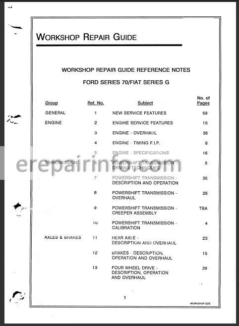
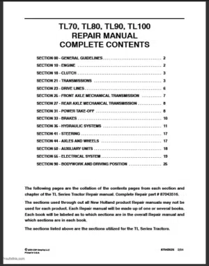
Contents
- – Service Features
Engines
Transmission
Rear Axle
Differential Lock
Brakes
Front Wheel Drive
Hydraulic Pumps
Remote Control Valves
Electronic Draft Control
Power Take O F F
Trailer Brakes
Electrical And Electronic System - – Engine Service Features
Specification
Performance
Cylinder Block
Crankshaft
Pistons
Connecting Rods
Cylinder Head
Inlet And Exhaust Valves
Camshaft
Rocker Arms And Shaft
Intake And Exhaust Manifolds
Lubrication System
Cooling System
Fuel System
Turbochargers And After Coolers - – Engine Overhaul
Engine Installation
Cylinder Block
Crankshaft
Pistons and Con R Rods
Camshaft
Lubrication
Cylinder Head and Valves
Turbocharger and Aftercooler
Cooling System - – Engine Timing
- – Engine Specifications
Introduction
Cylinder Block
Cylinder Head
Exhaust Valves
Intake Valves
Valve Springs
Valve Timing
Camshaft Lobe Lift
Installed Valve Recession
Valve Inserts
Valve Seats
Camshaft Idler Gear
Camshaft Gear
Rocker Arm Shaft
Rocker Arm
Tappets
Camshaft
Connecting Rods
Piston Pin
Pistons
Piston Rings
Crankshaft
Crankshaft Drive Gear
Main Bearing
Crankpin Bearings
Torsional Vibration Damper
Crankshaft Regrinding
Undersize Bearings Available
Flywheel
Oil Pump
Oil Pressure with Engine at Operating Temperature
Engine Oil Specifications
Selecting the Right Viscosity
Engine Oil Capacity
Thermostat
Water Pump
Fan Belt
Cooling System Capacities
Cooling F lu id
Torque Values - – Transmission Driving Techniques
- – Transmission Description And Operation
Clutches
Drive Lines
Vibration Damper
PTO Drive Line
Low Pressure Supply
Control Valve
Electronic Controls - – Transmission Overhaul
Valve Chest Removal
Transmission Overhaul Special Tools
Transmission Disassembly
Clutch Disassembly and Components
Clutch Piston Travel Check
Transmission Reassembly
Valve Chest Overhaul
Torque Specification - – Transmission Calibration
- – Rear Axle Description And Overhaul
Overhaul Special Tools
Disassembly, Centre Housing
Differential Assembly
Differential Lock Operation
Disassembly Axle Housing
Rear Axle Adjustments - – Brakes Description & Operation
Braking System Schematic Diagram
Power brake Valve Operation
Brake Valve Removal
Brake Valve Disassembly
Brake Assembly Axle Housing
Brake Plate Inspection
Handbrake Removal
Handbrake Installation
Handbrake Adjustment - – Four Wheel Drive Axle Description
Introduction
Super Steer
FWD Operation (Electrical)
FWD Engagement
Drive Line Ratios
Wheel Slip Calculations
Service Tools
Front Axle Disassembly
Differential Overhaul
Differential Adjustments & Reassembly
Drive Shaft Overhaul
Swivel Bearings
Swivel Housing Overhaul
Hub Overhaul
Planetary Reduction Overhaul
Axle Reassembly
FWD Clutch Unit Overhaul - – Hydraulic Pumps
Hydraulic Circuit Description
Hydraulic Pump Installation
Hydraulic Pump Drive Line
Variable Flow Pump Operation
Piston Pump Overhaul
Gear Type Pump Overhaul
Pump Drive Gear Housing Bearing Adjustment - – Electronic Draft Control System
Components
System Operation and Oil Flows
Overhaul
Electronic Draft Control Menu Modes
Hydraulic Lift Calibration
Electronic Draft Control Memory Reset
Adjustment to Speed of Response of EDC Valve
Fault Codes - – Into And Low Pressure Hydraulic System
Low-Pressure Hydraulic CIRCuit
Controls
PTO Schematic
PTO Components
PTO Clutch Oil Flow Diagrams
PTO Housing Removal
Disassembly
Inspection and Reassembly
Installation
PTO Output Shaft Removal ( rpm PTO Tractors)
PTO Output Shaft Seal Replacement
Pressure Testing - – Hydrostatic Steering Description & Overhaul
Components Location
Steering Motor
Priority Valve
Oil Flows
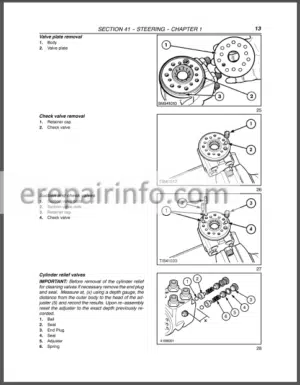
Steering Motor Disassembly
Steering Motor Reassembly
Steering Cylinder
Toein Adjustment
Steering Stop Adjustment - – Remote Control Valves
Features
Control Valve Identification
Remote Control Valve Oil Flows
Overhaul - – Trailer Brakes Description
Trailer Brake System
Trailer Brake Valve Pilot Head Operation
Trailer Brake Valve Operation
Trailer Brake Valve Disassembly
Bleeding the Brakes
Trailer Brake Pressure Test - – Electrical System Description
Instrumentation and Controls
Fuses, Relay and Diagnostic Connector
Harnesses and Connectors - – Electrical System Wiring Diagrams
Harness Identification
Symbols
Fuses
Connectors
Circuits
Basic (Permanent) Live Circuits
Accessory ‘on’
Engine Starting
Lighting
Work Lamps
Hazard Warning Lights
Pto Operation
Brake Lights
Diff Lock Operation
Front Wheel Drive Operation - – Electronic Instrument Cluster
Introduction and Component Location
Electronic Instrument Cluster Warning Lamps
Data Displays
Alarms
Service Diagnostic Modes - – Fault Finding And Diagnostics Procedure
- – Fault Finding Hydraulic Lift/Edc
- – Fault Finding Right Hand Controls
- – Fault Finding Electronic Instrument Cluster
- – Fault Finding Electronic Transmission Control
- – Fault Finding Engine Control
- – Hydraulic Pressure Testing
What you get
You will receive PDF file with high-quality manual on your email immediately after the payment.


Reviews
There are no reviews yet