Factory Service Repair Manual For New Holland MH2.6, MH3.6. Tons of illustrations, instructions, diagrams for step by step remove and install, assembly and disassembly, service, inspection, repair, troubleshooting, tune-ups.
Format: PDF
Language: English
Pages: 915
Searchable: Yes
Number: 87730662A
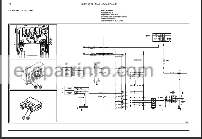
Wiring Diagrams: Yes
Hydraulic Diagrams: Yes
Model
New Holland MH2.6, MH3.6
Contents
- Main Operating Rules
Introduction
Foreword
Manual Handling - Safety
Precautions
Safety Precautions
Safety Decals - Features And Data
Identification Data
Noise Levels
Summary Plate For Maintenance Operations
Wheeled Excavator Main Components
Technical Specifications
Operating Weights
Digging Performance
Transport Dimensions
Bucket Usefulness Depending On Arm
Filling Chart - Upper Structure
Upper Structure
Main Frame And Counterweight
Power Unit
Engine
Radiator
Hydraulic Pumps
Main Pump
Double Pump With Gears
Air Cleaner
Exhaust Silencer
Hydraulic Oil Tank
Fuel Tank
Fuel Transfer Pump
Guards And Covers
Cab
Swinging Assy
Main Control Valve
Slew Device
Slew Hydraulic Motor
Slew Reduction Unit
Control Lever
Control Pedal
Steering Unit
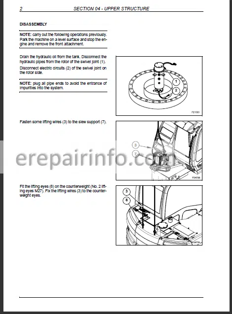
Swivel Joint
Features And Data
Brake Pedal Valve
Accumulators
Pressure Switches
Solenoid Valves - Undercarriage
Slewing Bearing
Lower Frame
Travel Assy
Travel Hydraulic Motor
Speeds Gear Box
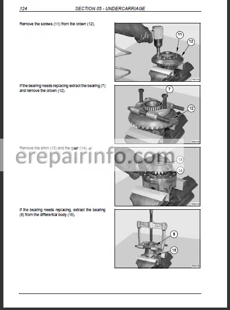
Steering Axles: Front And Rear
Rigid Rear Axle
Drive Shaft
Wheels And Tyres
Tyres
Blade
Lateral Stabilizers - Front Attachment
Introduction
Cylinder Removal And Installation
Bucket Cylinder
Arm Cylinder
Positioning Cylinder
Boom Cylinder
Cylinders
Bucket Cylinder
Arm Cylinder
Positioning Cylinder
Boom Cylinder
Antidrop Valve
Pins And Bushings
Buckets - Hydraulic System
Hoses And Fittings
Hydraulic System
Main Pipelines
Suction And Delivery Pipelines
Return Pipelines
Draining Pipelines
Front Attachment Pipelines
Nibbler/Breaker Control Pipelines
Slew Control PipelinesTravel And Blade/Stabilizers
Steering Pipelines (Machine Wd)
Steering Pipelines (Machine Wd)
Brake Pipelines
Power Steering Pipelines
Lateral Stabilizers And Blade Control Pipeline
Lock Valves
Stabilizers/Blade Selection Valve
Front Axle Lock
Axle Lock Valve
Pressure Relief Valve
Operation Of Circuits - Electrical System
Safety Precautions
Features And Data
Components Location And Operation
Undercarriage Electric Components
Machine With Four Steering Wheels
Machine With Two Steering Wheels
Control Units Electric System
Light And Beams Group
Gauges And Controls
Dashboards
Control Levers
Switches And Control Lights Panel
Switches And Warning Lamps
Monitor Panel
Key Start Switch
Left Control Lever
RightHand Control Lever
Control Panel And Switches
Machine Control Card
Pump Control Card
Electric Components
Throttle Lever Control
Swivel Joint
Batteries
Generator
Starter
Control Line And Wiring Harnesses
Controls On Consoles
Controls For Side Panel Switches
AntiTilting Check Control Line
Working Lights Control Line
Traffic Beams Control Line
Steering Column Controls - Troubleshooting
Introduction
Hydraulic System Troubleshooting
Electrical System Troubleshooting - Performance Test
Introduction
General Information For Machine Testing
Standard PerformancesMh
Table Of Excavator Standard Performances
Hydraulic Components Standard Performance
Main Pump PQ Curve
Standard PerformancesMh
Table Of Excavator Standard Performances
Hydraulic Components Standard Performance
Main Pump PQ Curve
Preparation For Performance Test
Excavator Performance Test
Engine Performance
Swing Performance
Front Attachment Performance
Control Levers
Boom/Slew Performance
Combined Slew/Boom Test
Steering
Brakes System
Gear Box
Gear Box Pressure Check
Components Performance
Overpressure Valve And Pilot Control Line
Overpressure Relief Valves
Drive Shaft
Hydraulic Pumps
Travel Motor
What you get
You will receive PDF file with high-quality manual on your email immediately after the payment.



Reviews
There are no reviews yet