Factory Service Repair Manual For New Holland MHCity MHPlus MH5.6. Tons of illustrations, instructions, diagrams for step by step remove and install, assembly and disassembly, service, inspection, repair, troubleshooting, tune-ups.
Format: PDF
Language: English
Pages: 687
Searchable: Yes
Number: 60413575
Wiring Diagrams: Yes
Hydraulic Diagrams: Yes
Model
New Holland MHcity, MHplus, MH5.6
Contents
- Safety Instructions
Personal Safety Instructions
Observe The Safety Instructions
Protection From Noise
Preparing For Emergencies
Wearing Protective Clothing
Safety Instructions Before Starting Work
Checking The Machine
Keeping The Working Area Clean
Using Grab Handles And Steps
Adjusting The Operator’S Seat
Applying The Safety Belt
Working From The Operator’S Seat Only
Never Take Passengers On The Machine
Safety Instructions For Machine Operation
Before Setting Off
Note The Position Of The Working Equipment
Taking Care During Operation
Taking Care When Trenching
Distance From Overhead Power Lines
Accident Prevention When Reversing And Slewing
Rules For Driving On The Road
Recovering And Towing The Machine
Travelling Uphill And Downhill
Preventing The Machine From Overturning
Inspecting The Deployment Location
Parking The Machine Safely
Preventing Accidents When The Machine Is Moving
Confirming The Direction Of Machine Travel
Avoid Caving Out High Banks
Protection From Rockfall And Landslides
Caving Prevention
Never Move The Bucket Above Persons
Safety Instructions, Maintenance/Servicing
Safety During Transport
Safety During Servicing Operations
Warning Instructions For Servicing Work
Correct Machine Support
Working At Greater Heights
Keeping Clear Of Moving Parts
Prestressed Units
Never Remove Lead Seals
Safety Instructions For Accumulators
Dismantling Components
After Repair Work
Correct Waste Disposal
Welding Operations
Starting The Engine With Starter Batteries
Prevention Of AcidInduced Burns
Prevention Of Scalding
Safe Handling Of Fluids
Fire Prevention
Evacuation In Case Of Fire
Risks From Exhaust Gases
Risks From Fluids In Pressure Systems
Preventing Heat Build Up Close To Pressure Systems
Preventing Heat Build Up In Lines Carrying Combustible Fluids
Removing Paint Before Welding
Risks From BreakingAway Components
Use Appropriate Tools
Warning And Instruction Signs
Signs
Positioning Of Signs
Organizational Measures
Selection And Qualification Of Personnel; Basic Responsibilities
Safety Instructions Governing Specific Operational Phases
Warning Of Special Dangers - Technical Data And Special Tools
Data Sheet For Cylinders
Bucket Induced Protrusion
Si And Additional Units
Quantities Of Space And Mass
Time Related Quantities
Quantities Of Force, Energy And Power
Conversions Tables
Conversion For Units Of Legth
Conversion For Units Of Area
Conversion From Foot And Inch To Metric Mesures
Conversion From Newtonmeter (Nm) Into Foot Pounds (Ft Lb)
Conversions Tables
Conversion Table For Units Of Pressure In Gases, Steam And Fluids
Conversion Table For Units Of Power, Energy And Heat Quantity
Conversion Table For Units Of Mechanical Stress
Practically Equivalent Units For Pressure And Mechanical Stress (Stregth)
Units Of Temperature And Conversion Formulars
Power, Energy And Heat Flow
Speed
Units Of Mass (Weight)
Units Of Volume, Flow Rates
Fuel Consumption
Calculation Examples
Angles Of Slope
Travel Speed
Hydraulic Outputs (Pumps/Motors)
Stroking Times Of Cylinders
Speeds Of Hydraulic Motors
Tightening Torques
General Information
Units Of Measurement
Bolts With Standard Thread
Bolts With Metric Fine Thread
Tightening Torques For Sae Flange System
Tightening Angles
Special Tools For Cylinders
Screwed Hex Insert For Piston Nut
Sealing Kit
Scraper Ring
Bushes
Rod Guide
Piston Nut Loosening And Tightening
Special Tools For Axles And Gearboxes
Axial Stress Meter
Bearing Friction Moment Adjusting Device
Driving Tool For Bushing
Assembly Aid For Shaft Seals
Master Shaft
Extraction Device
Driving Tool
Assembly Aid
Brake Centering Device
Tool Handle
Hydraulic Pump
Measuring Device
Threaded Studs
Driving Tool For Shaft Seals
Driving Tool - Machine Structure
Description Of The Machine (Mhcity Boom Adjusting Equipment)
Machine Layout
Undercarriage
Superstructure
Hydraulic System
Steering
Service Brake
Parking Brake
Floating Axle
Electrical System
Working Equipment
Description Of The Machine (Mhcity Monoblock Boom)
Machine Layout
Hydraulic System
Steering
Service Brake
Parking Brake
Floating Axle
Electrical System
Working Equipment
Description Of The Machine (Mhplus / Mh Boom Adjusting Equipment)
Machine Layout
Hydraulic System
Steering
Service Brake
Parking Brake
Floating Axle
Electrical System
Working Equipment
Description Of The Machine
Machine Layout
Hydraulic System
Steering
Service Brake
Parking Brake
Floating Axle
Electrical System
Working Equipment
Switches / Keys
Control Elements / Iso
Multifunction Display
Superstructure Components
Engine Assembly Components
Drive Unit Components, Overview
Mhcity - Electrical System
Automotive Electrical Systems
Cable Harnesses
Fuses
Checking / Replacing The Fuses
Table Of Fuses
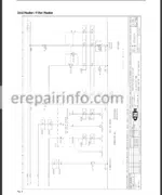
Electrical Circuit Diagrams
Table Of Contents
Power Supply / Starter Engine
Grid Heater / Filter Heater
Sensor Power Supply
Tank Sensor / Refuelling System
Pilot Control Shutoff
Pcs
Switches
Speed Adjusting Motor
Horn / Power Supply
Driver’s Cab
Steering Column Lever Switch
Lighting
Speedometer – Creep Speed
Valves / Air Filter Control
Speed / Floating Axle / Brake
Blower And Air Conditioner
Auxiliary Heating (Option)
Hammer / Shears / Frequency (Option)
Stabilizers / Levelling Blade
Esx Power Supply
Esx Can
Esx Coding
Esx Valve Control
Esx Pcs Valve Control
Esx Valve Stacking
Esx Valve Control
Esx Slewing Initiator
Esx Pressure Sensors
Can Bus / Power Supply, Overview
Fuses, Overview
Ground Points, Overview
Electrical Circuit Diagrams
Table Of Contents
Power Supply / Starter Engine
Grid Heater / Filter Heater
Sensor Power Supply
Tank Sensor / Refuelling System
Pilot Control Shutoff
Pcs
Switches
Speed Adjusting Motor
Engine / Power Supply
Steering Column Lever Switch
Lighting
Speedometer – Creep Speed
Valves / Air Filter Control
Speed / Floating Axle / Brake
Blower And Air Conditioner
Auxiliary Heating (Option)
Hammer / Shears / Frequency (Option)
Stabilizers / Levelling Blade
Esx Power Supply
Esx Coding
Esx Valve Control
EsxPcs Valve Control
Esx Valve Stacking
Esx Valve Control
Esx Slewing Initiator
Esx Pressure Sensors
Can Bus / Power Supply, Overview
Fuses, Overview
Ground Points, Overview
Electrical Circuit Diagrams
Layout Of Electrical Components
Electrical System Central Electronics (Behind Driver’s Seat)
Electrical System For ElectroHydraulic Pilot Control
Electrical System Of Pilot ControlUnit,Solenoid Valves, Sensors And Switches
Electrical System In Engine Compartment
Electrical System For Undercarriage Control Block
Electrical System For Undercarriage Stabilization
Electrical Components By Code Numbers
Pin Assignment Tables
Connector - Electronics
Electronic Control Unit
Esx Controller
Central Electronic System / Central Unit
Pcs
Can Bus (Digital Technique)
Electronic Control Diagram
Can Bus Wiring
Power Supply
Electrical Circuit Diagram CanBus Power Supply
Power Supply And Can Bus In Acc
Grounding
Components At Can Bus
Central Electronics
Description
MultiFunction Display
Description
Key Board Modules
Pcs, Power Control System With LoadLimit Regulator
Diagnosis Socket
Esx Controller
Components At CanBus
Right Joystick A For Boom And Bucket Cylinder
Right Joystick, Description
Left JoystickFor Stick Cylinder And Slewing Mechanism
Left Joystick, Description
Joystick Characteristics
Left Joystick
Right Joystick
Description
Functioning Principle Of Joysticks And Pedals
Description
Driving Pedal (Master)
Characteristic
Double Pedal (Slave)For Adjusting Cylinder Or Hammer/Shears
Description
Esx Coding
Esx Coding
Pcs: Power Control System
Function Chart And Location Diagram Of Components
Function Listing, Description
Fundamental Principle Of Pump Control
Description
Regulating Circuit
Speed Characteristics Of The Engine Under Load
Detection Of The Load Status
Regulating Process
Pcs When Driving On The Public Highway
Pcs Performance Diagram
Pcs Components
LoadLimit Regulator
Speed Actuator
Speed Sensing
Speed Sensor (Pickup)
Coolant Temperature Sensing
Temperature Sensor
ChargeAir Temperature Sensing
Temperature Sensor
Hydraulic Oil Temperature Sensing
Temperature Sensor
Proportional Valve
Description
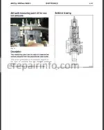
AV With Measuring Point X For Control Pressure
Description
Fan Control With Proportional Valve
Valve Cartridge
Hammer / Shears Control With Boom Adjusting Equipment (Spool Control Block) - Hydraulics
Working, Slewing And Pilot Control Circuits In The Superstructure
Schematic Diagram
Oil Flow Through Control Block
Description
Working, Travel And PilotControl Circuits In The Undercarriage
Schematic Diagram
Description
Hydraulic Circuit Diagram
Undercarriage
Drive Unit
Circuit Diagram
Description
MultiCircuit Pump Unit
Variable Displacement Twin Pump AVo
Drive Unit, Variable Displacement Twin Pump Output Regulator
Output Regulation
PilotControl Pump
Gear Pump
Hydraulic Reservoir With Attachments (Nos )
Description
Control Block
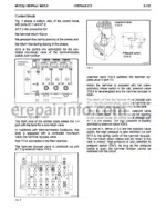
Control Block, Neutral Circuit (NosAnd )
Control Block Valves
Primary PressureLimiting Valves With Pressure Sequence Stage
Tank Channel – Preloading Valves
Secondary PressureLimiting Valves With Replenishing Stage (Sv)
Proportional Valves For Control Spool Adjustment
Pressure Sensors
PilotControl System
Schema
Pilot Control Unit
Schematic Diagram
Solenoid Valves And Their Functions
Proportional Valve Y Of The LoadLimit Regulator
Solenoids
Solenoid Valve
Travel Circuit OfKm/H Version
Schematic Diagram
Travel Control Spool
Hydraulic And Electric Rotor
Hydraulic Rotor
Electric Rotor
Travel Drive
Travel Oil Motor Type
Technical Data
Travel Oil Motor
Undercarriage Solenoid Valves
Steered Axle
FloatingAxle Cylinder
Travel Circuit
Schematic Diagram
Travel Control Spool With Replenishing Function For Forward Travel
Replenishing System
Travel Oil Motor Type AVm For / Km/H (No )
Technical Data
Travel Oil Motor
Braking, Steering And Fan Circuit
Schematic Diagram
Brake System
Pedal Brake Valve
Steering System
Priority Valve
Steering Valve
Fan System
Schematic
Fan Motor
Combined Radiator With Controlled Fan Drive
Replenishing System
Undercarriage, Stabilizers
Schematic Diagram
Stabilizer Control Spool
Levelling Blade Cylinder
Outrigger Cylinder (No )
Stabilization Variants
Boom Cylinder Circuit Without
Regeneration Circuit
Schematic Diagram
Description
Boom Cylinder Control Spool Without Regeneration Circuit
Boom Cylinder Circuit With Regeneration Circuit
Control Spool Details
Boom Cylinder Control Spool With Regeneration Circuit
Boom Check Valve With Emergency Operation Capability
Pipe Break Protection Valves (NosAnd )
Bucket Cylinder Circuit
Schematic Diagram
Bucket Cylinder Control Spool
Bucket Parallel Connection Circuit
Description
Restrictor NonReturn Valve
Switching From Backhoe Bucket To Grab
Stick Cylinder Circuit With Regeneration Function
Schematic Diagram
Stick Cylinder Control Spool
Stick Check Valve With Emergency Operation Capability
Description
Adjusting Cylinder Circuit With
Pressure Compensator And Relief Valve
Schematic Diagram
Boom Adjusting Cylinder
Boom Adjusting Cylinder Control Spool
Pressure Compensator
Function
Operation
Regulation
Pressure Compensator, Relief Valve And Ls Pressure Limiting Valve
Relief Valve
Pipe Break Protection Valve
Combined Functions
Parallel Actuation Of Boom, Bucket, Adjusting And Stick Cylinder
Hydraulic Hammer Circuit
Schematic Diagram
Hydraulic Hammer Control Spool
Hammer Circuit With Auxiliary Function
Schematic Diagram
Hammer Circuit With Auxiliary Function Like Shears Or Crusher With
Boom Adjusting Equipment, Description
Hammer/Shears Control Spool
Control Block
Hammer ByPass Valve
Shears / Crusher Circuit (Boom Adjusting Equipment)
Shears / Crusher Control Spool
Hydraulic Hammer Circuit
Hydraulic Hammer Control Spool
Hammer Circuit With Auxiliary Function
Hammer Circuit With Auxiliary Function Like Shears Or Crusher With
Monoblock Boom Equipment, Description
Hammer / Shears Control Spool
Control Block
Hammer ByPass Valve
Shears / Crusher Circuit
Schematic Diagram
Shears / Crusher Control Spool
Slewing System
Schematic Diagram
Slewing Pump
Slewing Pump Valves
FeedPressure Limiting Valve
Secondary Valve
Pressure CutOff Valve
Slewing Pump Control Unit
Pressure Control Valve
Slewing Gearbox
Oil Motor
Integrated Holding Brake
Speed Sensor
Grab Rotation Mechanism
Schematic Diagram
Solenoid Valve For Grab Rotation (No )
Grab Rotation Motor - Calibration
Measures To Be Taken On Main Pump AV
Adjustment Of The Setscrews And Currents
Measures To Be Taken On Slewing Pump
Setting Of Mechanical Zero Position
Display, Service, Calibration
General Information
Display, Service, Calibration (Engine On)
Setting Of Calibration Parameters
Calibration (Engine On)
Display, Service, Calibration (Engine Off)
Setting Of Calibration Parameters
Calibration (Engine Off) - Troubleshooting
General Information On Fault Codes
Fault Codes
Fault Codes Pcs Unit
Fault Codes, Central Unit - Repair Instructions
Welding Operations
General Welding Instructions
Protecting Electronic Modules During Welding Operations
Effect Of Electromagnetic Fields And Electrostatic Discharges
Handling Of Oils And Greases
Securing The Machine
Depressurizing The Hydraulic System / Brake System
Depressurizing The Hydraulic System
Bearings And Bushings
Removal Of Bearings And Bushings
Fitting Of Bearings And Bushings
Superstructure Components
Replacing The Buffers Under The Cab Baseplate
Preparations
Front Buffers
Rear Buffers
Removing And Refitting The Cab
Preparations
Separation Of Water Pump
Unplugging The Electrical Connectors
Dismantling The Cab
Refitting The Cab
Driver’s Seat
Steering Column, Steering Valve
Control Levers
Esx Box
LoadLimit Regulator
Fan Door
Combined Radiator
Battery Box
Battery Box Panelling
The Metal Panel
Refitting The Metal Panel
Link Between Superstructure And Undercarriage Components
Rotor
Slewing Gearbox
Dismantling And Assembling The Slewing Gearbox
BallBearing Slewing Ring
Fitting The BallBearing Slewing Ring
Undercarriage Components
Axles And Gearboxes
Instructions For The Repair Of Gearboxes And Axles
Testing Procedures
Service Brake
Brake Disks, Checking The Lining Thickness
Bleeding The MultipleDisk Brake
Cardan Shaft
Refitting The Cardan Shaft
Rigid Axle
Tightening Torques
Refitting The Rigid Axle
Rigid Axle, Hydraulic Motor And Flanges
Rigid Axle, Gearbox Housing
Ridid Axle, Differential Unit
Rigid Axle, Pinion Unit
Steered Axle
Tightening Torques Alpp
Refitting The Steered Axle
Steered Axle, Steering Cylinder
Steered Axle, Reducer Gear
Steered Axle, Articulated Joint Housing
Steered Axle, Differential Unit
Steered Axle, Pinion Group
FloatingAxle Cylinder
Replacing The Rod Seal
Repairing The Check Valve
Recommissioning And Bleeding
Speed Sensor
Tyres And Wheels
Tyres And Wheels, Safety Instructions
Tyre Pressure, Checking And Topping Up
Tyres – Sizes / Pressures / Travelling Speeds
Changing A Wheel
Table Of Tightening Torques
Fastening Of Wheels
Steps, Left Side
Installing The Steps On The Left Side
Steps, Right Side, ToolBox
Dismantling The ToolBox
Stabilizers
Safety Instructions
Levelling Blade
Outriggers
Levelling Blade
Refitting The Levelling Blade
Outrigger Cylinders
Outrigger Cylinder Components
Outrigger Cylinders, Tightening Torques
Levelling Blade Cylinders
Levelling Blade Cylinder Components
Levelling Blade Cylinders, Tightening Torques
Equipment, Components
Boom Cylinders For Monoblock Boom Equipment
Boom Cylinders For Boom Adjusting Equipment
Boom Cylinder
Boom Cylinder, Components
Dismantling The Boom Cylinder
Tightening Torques
Stick Cylinder
Refitting The Stick Cylinder
Stick Cylinder, Components
Tightening Torques
Assembling The Stick Cylinder
Bucket Cylinder
Refitting The Bucket Cylinder
Bucket Cylinder, Components
Dismantling The Bucket Cylinder
Tightening Torques
Adjusting Cylinder
Refitting The Adjusting Cylinder
Boom Adjusting Cylinder, Components
Dismantling The Boom Adjusting Cylinder
Tightening Torques
Assembling The Boom Adjusting Cylinder
SlipOn Tooth
Safety Instructions
Replacing The SlipOn Teeth
Trenching Grab, Wear Limits
Reworking The Stops
Fuses
Checking And Replacing The Fuses
Location Of Fuses And Modules In The Cab And In The Engine Compartment
Fuses, Table
Lamp Bulbs
Replacing The Lamp Bulbs, Instructions
Bulb Table
Replacing The Headlamp Bulb
Replacing The Lamp Bulb In The Front Direction Indicator Lamp
Replacing The Lamp Bulb Of The Cab Interior Lamp
Replacing The Lamp Bulb Of The TailLight
Replacing The Lamp Bulb Of The Cab Floodlamp
Replacing The Lamp Bulb Of The Boom Floodlamp
Engine
What you get
You will receive PDF file with high-quality manual on your email immediately after the payment.






Reviews
There are no reviews yet