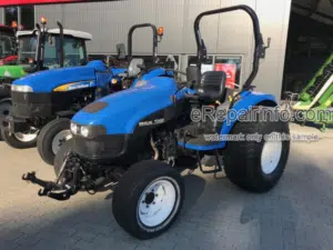
Repair Manual For New Holland TC35A, TC35DA, TC40A, TC40DA, TC45A, TC45DA.
This repair manual provides the technical information needed to properly service and repair the New Holland tractors. Use this manual in conjunction with the operators manual for complete operation, adjustment, and maintenance information.
Format: PDF
Language: English
Pages: 1478
Bookmarks: Yes
Searchable: Yes
Number: 87618716; 86618104
Wiring Diagrams: Yes
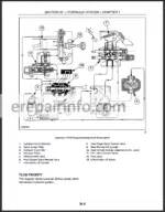
Hydraulic Diagrams: Yes
Model
New Holland TC35A, TC35DA, TC40A, TC40DA, TC45A, TC45DA
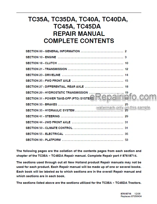
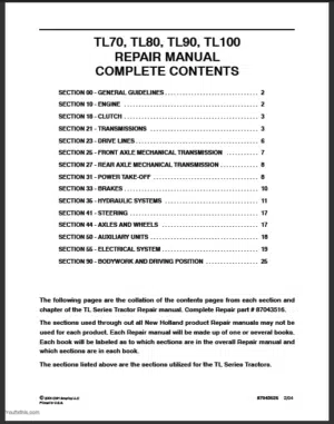
Contents
- General information
- Engine N843L, N844, N844L
- Clutch
- Transmission
- Driveline
- FWD front axle
- Differential rear axle
- Hydrostatic transmission
- PTO systems
- Brakes
- Hydraulic system
- Steering
- 2WD front axle
- Climate control
- Electrical Platform
Chapters
- – General Information
Introduction
Safety
Technical Information
Safety Precautions
Safety Decals
Instruction Decals
Specifications
General Dimensions
Minimum Hardware Tightening Torques
Special Tools
Lubricants
Recommended Lubricants
Adjustments
Tire Inflation Pressure
PreSeason And PreDelivery Checklist - – Engine
Specifications
Metric Bolt Torque Specifications
Compression Test And Tools
Description Of Operation
Troubleshooting
Cylinder Head And Valve Train Components
Cylinder Block Assembly
Separating The Tractor At The Clutch Housing/EngineX Transmission
Separating The Tractor At The Hst Housing/EngineHst Transmission
Separating The Tractor At The Hst Engine Frame
Attaching The X Transmission To The Engine
Attaching The Hst To The Engine
Fuel Injector And Glow Plug
Oil Pressure Switch
Temperature Sending Switch And Alternator
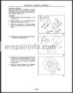
Fan, Water Pump And External Oil Tube
Air Inlet Manifold
Rocker Arm Shaft And Support Bracket
Cylinder Head
Valve Tappet
Fuel Shutoff Solenoid
Engine Timing Gear Cover, Timing Gears, And Cam Shaft
Timing Gear Cover Removal
Timing Gears And Cam Shaft
Oil Sump
Oil Suction Pipe And Strainer
Balancer Assembly
Connecting Rods, Bearings, And Pistons, Rings
Flywheel
Backplate And Oil Seal
Crankshaft Main Bearings
Cylinder Head
Inspection And Repair
Valve Seats
Valves
Valve Guides
Valve Springs
Rocker Arms
Push Rods
Cylinder Head
Cylinder Block
Pistons
Piston Rings
Connecting Rods
Connecting Rod Bearing
Clearance Check
Pistons, Rings, And Connecting Rod
Main Bearing And Thrust Washer
Crankshaft
Bearing (Bushing)
Main Bearing
Port Block
Timing Gear
Camshaft
Flywheel
Timing Gear Housing
Front Oil Seal And Steering Pump Seal
Crankshaft And Bearing Holder
Rear Oil Seal And Backplate
Flywheel
Pistons And Connecting Rods
Balancer Assembly
Balancer Shims
Oil Suction Pipe And Suction Strainer
Oil Sump
Camshaft And Camshaft Gear
Idler Gear, Oil Pump, And Injection Timing
Timing Gear Cover
Crankshaft Pulley
Fuel Injection Pump
Hydraulic Oil Pump
Power Steering Pump
Head Gasket Selection
Selection Chart
Cylinder Head
Valve Clearance
Valve Cover
Water Pump And Cooling Fan
External Oil Tube
Glow Plug And Connector
Fuel Injector
Fuel Piping
Alternator And Temperature Sender Switch
Exhaust Manifold
Description Of OperationEngine Lubrication System
Oil Filter
Construction And Function
Oil Pump
Engine Oil Pressure
Check
Oil Pressure Relief Valve
Oil Consumption
Description Of OperationCooling System
Radiator Cap
Thermostat
Water Pump
Cooling Fan
Radiator
Water Pump
Thermostat
Cab Heater
Fuel Variation Mechanism
Delivery Valve Assembly
Ctd (Compact Timing Device)
Pumping Elements
Delivery Valves
Injection Pump
Fuel Pump
SpillTiming Procedure
Fuel Screw/High Idle
Fuel Pump
Auto Bleed
Description Of Operation
Governor
Injectors
Engine Breather Valve
Engine Breather Valve - – Clutch
Bolt Torques
Separating The Tractor At The Clutch Housing/Engine
Attaching The X Transmission To The Engine
Clutch Related Components
Pilot Bearing
Damper Disc
Flywheel Dimensions
Clutch Release Bearing
Clutch Linkage Components
Cross Shaft Bushings
Pedal Bushings
Pedal
Maximum Travel Adjustment - – Transmission
Metric Bolt Torque Specifications
Cross Section
Powerflow
Separating The Tractor At The Clutch Housing/Engine
Clutch Housing
Main Transmission
Retainer Cover
Main Shift Rails And Shift Forks
Main Shaft
Range Shift Rail And Shift Fork
Range Gear Countershaft
Input Shaft
Reverse Idler Shaft
Shuttle Shift Rail And Fork
Main Countershaft
Synchronizers
Main Transmission Components
Synchronizers
Main Countershaft
Shuttle Shift Rail And Fork
Reverse Idler Shaft
Input Shaft
Main Countershaft End Float
Range Gear Countershaft
Range Shift Rail And Fork
Main Shaft
Main Shaft End Float
Main Shaft Gears End Float
Main Shift Rails And Forks
Retainer Cover
Clutch Housing
Attaching TheXTransmission To The Engine
Transmission Shift Levers
Main Shift Control Lever
Main Shift Lever
Shuttle Shift Control Lever - – Driveline
Front Wheel Drive Take Off Gearbox
Sensitrack
Automatic Position
Full Time Front Wheel Drive (Locked Down)
Supersteer™ Front Axle
Troubleshooting
Lubrication
Front Wheel Drive Take Off Gearbox
Sensitrack - – Fwd Front Axle
Front To Rear Axle Ratio
Bolt Torque Specifications
Special Tools
Standard Fwd Axle
Gear Reduction Drop Box
Front Axle And Differential
Drive Pinion
Front Axle
Differential
Gear Reduction Drop Box
Drive Pinion
Differential Gear
Axle And Differential
Differential Case Bearing Preload
Check And Adjustment
Ring GearToPinion Backlash
Check And Adjustment
Gear Reduction Box
Ring GearToPinion Backlash
Bevel GearToPinion Backlash
Supersteert/Sensitrackt
Supersteert
Sensitrackt
Automatic Position (Engaged)
Automatic Position (Disengaged)
Full Time Front Wheel Drive (Locked Down)
Supersteert Front Axle
Supersteert Axle
Gear ReductionDrop Box
Front Axle And Differential
Drive Pinion
Front Axle
Gear ReductionDrop Box
Drive Pinion
Differential Gear
Axle And Differential
Differential Case Bearing Preload
Check And Adjustment
Ring GearToPinion Backlash
Check And Adjustment
Gear Reduction Box
Bevel GearToPinion Backlash
Supersteert Axle - – Differential, Rear Axle
Differential
Differential Lock
Rear Axle
Differential
Drive Pinion
Rear Axle
Final Pinion - – Hydrostatic Transmission
Power Flow
High Range
Low Range
Oil Flow
Neutral Position
Forward Position
Reverse Position
Variable Displacement Pump
Two Position Displacement Motor
Hi/Lo Speed Control/Control Pod
Hi/Lo Speed Control
Foot Control Pedals
Charge Pump Relief Valve
Pressure Testing And Adjustments
High Pressure Relief Valve
Hi/Low Pressure Test
Separating The Tractor
Separating At The Hst Housing/Engine
Separating The Hst Housing At The Gearbox
Attaching The Hst Housing To The Gearbox
Attaching The Hst To The Engine
Hydrostatic Transmission
Charge Pump
Port Block
Cylinder Block Assembly
Motor Swash Plate
Input And Output Shaft
Pump Swash Plate
Port Block
Piston
Charge Pump
Swash Plate
Pump Shaft (Input Shaft)
Charge Pump
Cylinder Block Assembly For Pump
Motor Shaft
Cylinder Block Assembly For Motor
Assembly For Motor
Port Block
Hydrostatic Transmission
Check Valve
Gearbox
Gearbox Identification
Hi/Lo Solenoid Valve
Adapter Block
Cruise Control
Electromagnet Air Gap Adjustment
Hst Pedals
Stop Adjustment
Hst Cruise Control Magnet
Hst Foot Control Pedals
Neutral Adjustment
Hst Pedals Return Spring - – Power TakeOff (Pto) Systems
Pto Hydraulic System
Pto Clutch
Metric Bolt Torque Specifications
Rear Pto
Power Flow Diagram For The X Synchronized Shuttle Shift Transmission
Power Flow Diagram For The Hydrostatic Transmission (Hst)
Power Flow Diagram For Tractors Equipped With A Mid Pto Kit
Hydraulic Fluid Flow
Pto Clutch Assembly
Pressure Testing
Test Procedure
Pto System Diverter Valve Assembly
Pto Clutch Control Valve (Bsn)
Clutch Control Relief Valve
Pto Clutch Control Valve (Asn)
Pto Clutch
Pto System System For X Synchronized Shuttle Shift Transmission
Pto Input Shaft
Pto Countershaft And Rear Pto Shaft
Countershaft
Pto System For Hydrostatic Transmission (Hst)
Pto Input Shaft
Pto Countershaft And Rear Pto Shaft
Disassembly
Mid Pto Countershaft And Drop Box - – Brakes
Specifications
Bolt Torque Specifications
Description of Operation
Brakes
Parking Brake
Overhaul
Brakes
Removal and Disassembly
Inspection
Assembly and Installation
Adjustment - – Hydraulic System
Flow Priority
Hydraulic System
Hydraulic Fluid Filter
Combination System Relief Diverter Valve Manifold Assembly
Control Valve Assembly (Hpl)
Fluid Flow
Neutral Position
Raising Position
Lowering Position
Bypass SpoolFluid Flow
Closed Position
Open Position
Flow Control Valve
Single Lever Position Control
Neutral Position To Raise
Raise Position To Neutral Position
Neutral Position To Lowering Position
Dual Lever Position Control (Draft Control)
Top Link Sensing Raise
Top Link Sensing Lower
Varying Draft Control Settings
Combining Position And Draft Control Settings
Pressure Testing
Main System Relief Valve
Inlet Restriction
Pump Efficiency
Lift Cylinder
Flow Control Valve
Hydraulic Control Valve
Combination System Relief And Diverter Valve Assembly
Pto System Diverter Valve
Hpl Linkage
Control Lever
Description Of OperationHydraulic Pump And Filter
Hydraulic Pump And Filter
Hydraulic Pump
Sump Tube And Screen Filter
Remote Valves
Rear (SingleSpool) Remote Valve
Front (DoubleSpool) Remote Valve
Rear (SingleSpool) Remote System
Fluid Flow
Remote Cylinder Extending
Remote Cylinder Retracting
Front Remote (Two Spool) Loader Control Valve Fluid Flow Diagrams
Bucket Control
Neutral/Lift Control Neutral
Dumping/Lift Control Neutral
Dumping Regen/ Lift ControlNeutral
Roll Back/Lift Control Neutral
Neutral/Lift Control Raising
Neutral/Lift Control Lowering
Neutral/Lift Control Float
Rear (SingleSpool) Remote Valve
Front (Double Spool) Remote Valve - – Steering
Supersteert
Power Steering Control Motor
Spool And Sleeve
Rotor And Fixed Ring
Check Valve
Drive Shaft
Pressure Relief Valve
Power Steering Pump
Steering Cylinders
Wd And Standard Wd
Supersteert
Fluid Flow Neutral Position
Fluid Flow Left Turn
Fluid Flow Right Turn
Manual Operation
Power Steering Operation
Fluid Flow Neutral Position
Fluid Flow Left Turn
Fluid Flow Right Turn
Manual Operation
Troubleshooting
Pressure Testing
Pump, Steering Motor, And Relief Valve
Test Results
Steering Cylinder
Test Results
Lubrication
Lubricate EveryHours
Steering Control Motor
Steering Cylinder
Pump And Reservoir Tank
Pump Installation
Power Steering Tubes - – Front Axle
- – Climate Control
Refrigerant
Refrigerant Oil
Low Pressure Switch
High Pressure Switch
Compressor
Condenser
Evaporator
Expansion Valve
Receiver/Drier
Heater
Heater System
Hvac Control Panel
Cab Air Filter
Cleaning Cab Air Filter
Compressor Protection Switches
HighPressure Cutout Switch
LowPressure Cutout Switch
Component Location
Cab And Engine Bay
Cab Roof
Troubleshooting
Expansion Valve Testing
Temperature/Pressure Chart
Service Precautionary Statements
Leak Testing
Refilling
Contaminants
Preventing Mixing Of Service Equipment
Refrigerant Extraction And Recycling Equipment
Using Extraction Equipment
Using Recycling Equipment
Recycling Vs Reclaiming
Containment Of Air Conditioning Refrigerants
Recovery
Flushing
Recharging/Refilling
Using A Manifold Gauge Set
Checking Refrigerant For Excess Air
Containers For Storing Recycled Refrigerant
Disposal Of Empty Or NearEmpty Disposable Containers
Applicable Sae Standards
Related Sae Standards
Manifold Gauges And Interpretations
Performance Test Examples
Evacuating The Refrigerant
Vacuum Test
Pressure Test
Leakage Test
Charging
Belt Replacement
Hvac Controls
Heater Valve
Condenser
Receiver/Drier
Evaporator/Heater Core Replacement
Expansion Valve
Temperature Sensor
Blower Motor/Blower Motor Resistor
Low Pressure Switch
High Pressure Switch
A/C Compressor
Compressor Assembly Torques
Compressor Breakdown
Clutch Breakdown
Compressor Repaired Internally And Reinstalled In The System
Sanden Compressor Replaced By A New Sanden Compressor
Of The Same Type
Clutch Head Repair
Keyed Shaft Armature Removal
Rotor Assembly Removal
Field Coil Assembly Removal
Field Coil Assembly Installation
Rotor Assembly Installation
Armature Assembly Installation
Replacement Of Shaft Seal
Cylinder Head Removal
Valve Plate Removal
Valve Plate And Cylinder Head Installation - – Electrical
Wiring Harnesses
Grounds
Electrical System Components
Battery
Checking The Electrolyte Level
Main Fuse
Fuse Block
Key Switch
Terminal Identification
Stop Position (Not Shown)
Heat/ Accessory/ Run Position
Start Position
Light Switch (Road Lights)
Terminal Identification And Testing
Work Light Switch
Forward Position On
Headlight
Taillight
Hazard Light Switch
Off Position
On Position
Transmission Range Safety Switch (Hst And Gear)
Extended Position
Retracted Position (Not Shown)
Rear (Main) Pto Safety Switch
Testing
Extended Position
Retracted Position
Mid Pto Safety Switch (Optional For Da, Da, And Da Models Only)
Seat Safety Switch
Parking Brake Safety Switch
Relays
(Da) Series Relay Panel Identification
(A) Series Relay Panel Identification
TestingMicro Relays
Hi, Low, Cruise Control, Fuel Shutoff, Pto Safety, And Glow Plug Lamp Relays
Headlight And Neutral Start Relays
Glow Plug Power Relay
Diodes
Module Testing
Diode Testing
Operator Safety Module
Glow Plug Timer
Testing
Engine Glow Plugs
Hazard Flasher/Turn Signal Control Module
Fuel Level Sending Unit
Fuel Shutoff Solenoid
Engine Oil Pressure Switch
Engine Coolant Temperature Sending Unit
Hi/Low Transmission Range Switch
Optional Testing
Hi/Low Transmission Range Solenoid
Removal
Electric Cruise Control Switch (Hst)
Cruise Control Magnet (Hst)
Cruise Control Brake Release Switch
Extended Position (Not Shown)
Retracted Position
Complete Wiring Schematic
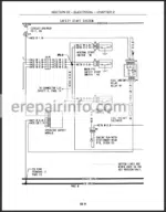
Safety Start Circuit (Operator Present)
Safety Start Circuit (Operator Not Present)
Safe Operation Circuit (Operator Present)
Safe Operation Circuit (Operator Not Present)
Glow Plug Circuit
Road Lights Circuit
Work Lights Circuit
Hazard Flasher Circuit
Right Turn Signal Circuit
Left Turn Signal Circuit
Pto Indicator Light Circuit
Engine Coolant Temperature Circuit
Engine Low Oil Pressure Indicator Light Circuit
Fuel Level Circuit
Parking Brake Indicator Light Circuit
Tachometer Circuit
Auxiliary Power Socket Circuit
Cruise Control Circuit (Hst Transmission)
Hst Range Low Shift Circuit
Hst Range High Shift Circuit
Charging Circuit
Component Operation And Servicing
Instrument Panel
Component Testing And Replacement
Fuel Gauge
Temperature Gauge
Tachometer
Instrument Panel Indicator And Illumination Lights
Bulb Identification Chart
Bulb Replacement
Alternator Specifications
Alternator Troubleshooting
Charging System
Alternator
Description Of Operation
Charging Circuit
Principle Of Ic Regulator
Preliminary Alternator Tests
Alternator Drive Belt
Alternator Output
Alternator Removal
Alternator Disassembly
Alternator Component Testing And Inspection
Stator
Rotor
Rectifier Assembly
Alternator Brushes
Alternator Bearings
Drive Pulley
Alternator Frames
Alternator Bench Check
Starter Motor Specifications
Starter Motor Troubleshooting
Starting System
Description Of Operation
Starter Components
Starter Motor Assembly
Starter Solenoid
Pinion Clutch
Armature
Brush Holder
Field Coil
Starter Solenoid
Assembly
No Load Test
Grounds
Electrical System Components
Battery
Checking The Electrolyte Level
Main Fuse
Fuse Blocks
Key Switch
Terminal Identification
Stop Position (Not Shown)
Heat/ Accessory/ Run Position
Start Position
Multifunction Stalk Switch (Lights, Turn Signals, Horn)
Switch Testing
Work Light Switch
Forward Position On
Installation
Headlight
Taillight/Rear Flasher Light
Front Flasher Warning Light/Turn Signals
Cab Work Lights
Hazard Light Switch
Off Position
On Position
Transmission Range Safety Switch
Extended Position
Retracted Position (Not Shown)
Rear (Main) Pto Safety Switch
Extended Position (Pto On)
Retracted Position (Pto Off)
Mid Pto Safety Switch (Optional)
Extended Position
Retracted Position
Seat Safety Switch
Parking Brake Safety Switch
(Da) Series Relay Panel Identification
TestingMicro Relays
Hi, Low, Cruise Control, Fuel Shutoff, Pto Safety, Glow Plug Lamp,
Flasher Cutoff, Park Brake Interface, Front Work Lights, And Hvac Relays
Headlight, High Beam, Neutral Start, And Cab Power Relays
Replacement
Glow Plug Power Relay
Installation (All Relays)
Diodes
Module Testing
Diode Testing
Operator Safety Module
Park Brake Safety Alarm (Buzzer)
Glow Plug Timer
Engine Glow Plugs
Hazard Flasher/Turn Signal Control Module
Fuel Level Sending Unit
Fuel Shutoff Solenoid
Engine Oil Pressure Switch
Engine Coolant Temperature Sending Unit
Hi/Low Transmission Range Switch (Hst)
Optional Joystick Switch Testing
Hi/Low Transmission Range Solenoid (Hst)
Electric Cruise Control Switch (Hst)
Cruise Control Magnet (Hst)
Cruise Control Brake Release Switch (Hst)
Extended Position
Retracted Position
Cab To Tractor Harness Main Connectors
Electrical Schematic Diagram
Safety Start Circuit (Operator Present Or Not Present)
Safe Operation Operator Present Circuit
Safe Operation Operator Not Present Circuit
Safety Alarm Circuit (Key Off And Park Brake Off)
Safety Alarm Circuit (Key On, Rear Pto On, Operator Not Present And Park Brake On)
Safety Alarm Circuit (Key On, Rear Pto On, Operator Not Present And Park Brake Off)
Glow Plug Circuit
Headlights Circuit (Position, Low And High Beams)
Front Work Lights Circuit
Cab Work Lights Circuit
Interior Cab Lights Circuit
Hazard Flasher Lights Circuit
Right Turn Signal Circuit
Left Turn Signal Circuit
Hvac Circuit
Auxiliary Power Socket Circuit
Front And Rear Wiper Circuit
Horn Circuit
Cruise Control Circuit (Hst Transmission)
Hst Range Low Shift Circuit
Hst Range High Shift Circuit
Charging Circuit
Pto Indicator Light Circuit
Park Brake Indicator Light Circuit
Engine Coolant Temperature Circuit
Engine Low Oil Pressure Indicator Light Circuit
Fuel Level Circuit
Tachometer Circuit
Beacon Circuit
Radio Circuit
Component Operation And Servicing
Component Testing And Replacement
Temperature Gauge
Replacement
Tachometer
Testing
Proof Meter (Hour Meter)
Instrument Panel Indicator And Illumination Lights
Bulb Identification Chart
Bulb Replacement
Alternator Specifications
Alternator Troubleshooting
Charging System
Description Of Operation
Charging Circuit
Principle Of Ic Regulator
Preliminary Alternator Tests
Alternator Drive Belt
Alternator Output
Alternator Removal
Alternator Disassembly
Alternator Component Testing And Inspection
Stator
Rotor
Rectifier Assembly
Alternator Brushes
Alternator Bearings
Drive Pulley
Alternator Frames
Assembly
Alternator Bench Check
Installation
Starter Motor Specifications
Starter Motor Troubleshooting
Starting System
Description Of Operation - – Platform
Hood
Rear Hood Side Panels
Dash Console
Seat
Rops
Fuel Tank
Fenders
Deck
Hood
Rear Hood Panels
Dash Console
Operator Seat
Front Wiper Motor
Washer Tank
Rear Wiper Motor
Door Handle And Latch
Door Striker
Cab Door
Cab Rear Window
Fuel Tank
Fenders
Cab
What you get
You will receive PDF file with high-quality manual immediatly after the payment.



Reviews
There are no reviews yet