Factory Service Manual For New Holland Tractor. Manual Contains Illustrations, Instructions, Diagrams For Step By Step Remove And Install, Assembly And Disassembly, Service, Inspection, Repair, Troubleshooting, Tune-Ups.
Format: PDF
Language: English
Pages: 638
Number: 87616423 — 01 — 2007
Bookmarks: Yes
Searchable: Yes
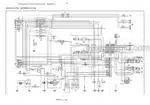
Wiring Diagrams: Yes
Model
New Holland Tractor
TD60D
TD70D
TD80D
TD90D
TD95D
Contents
-GENERAL
General Instructions
Notes For Spare Parts
Notes For Equipment
Safety Rules
Consumables
-ENGINE
General Specification
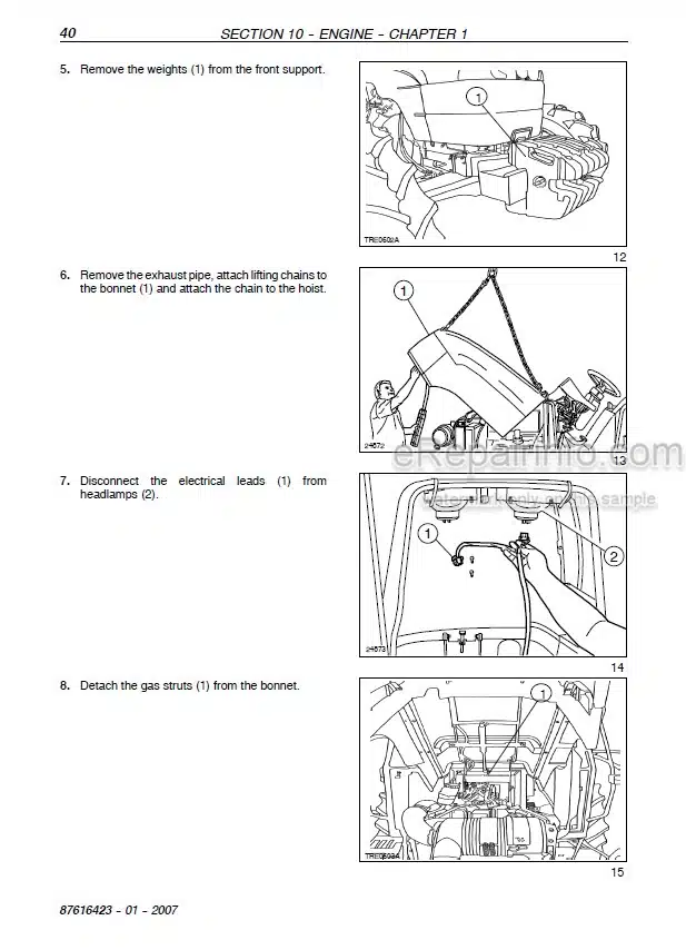
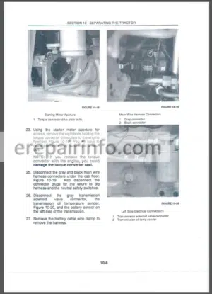
Engine Removal-Installation
Engine Bench Overhaul
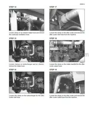
Radiator Removal-Installation
Crankshaft Front Oil Seal Removal Installation
Coolant Pump Removal Installation
Cooling System Thermostat
Bosch Injection Pump Removal Installation
Injectors Removal Installation
Valve Clearance Adjustment
Coolant Pump Overhaul
Compression Test
-CLUTCH
General Specifications
Removal – Installation
Adjustment Of The Main And PTO Clutch Control Linkage
-GEARBOX
Mechanical Transmission (12×4)
Reverser (12×12)
Reverser and Creeper (20×12)
-TRANSMISSION OF MOTION
Main Specification
Torque Settings And Tools
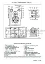
Cross-Sectional Views
Transmission Shafts And Guard (Disassembly – Assembly)
Drive Gear Housing (Removal – Installation)
Drive Gear Housing Removed (Disassembly – Assembly)
-FRONT MECHANICAL TRANSMISSION
Main Data
Tightening Torques
Tools
Cross-Sectional Views
Description And Operation
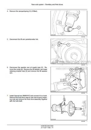
Complete Front Axle Removal – Installation
Front Axle Removal – Installation
Steering Knuckle Bearing Pins Replacement
Stub Axle Adjustment
Wheel Hub Bearing Adjustment
Bevel Drive Adjustment
Front Axle Differential Overhaul
Front Axle Differential With LIM-Slip Overhaul
Front Axle Differential With No Spin Overhaul
Leading Drive Wheels Toe-In Check
-REAR MECHANICAL TRANSMISSION
Main Data
Tightening Torques
Special Tools
Cross-Sectional Views
Description And Operation And Troubleshooting
Transmission-Gearbox Casing Removal-Installation
Transmission-Gearbox Casing Disassembly-Overhaul
Gearbox Driven Shaft End Float Adjustment
Differential Lock Engagement Sleeve Adjustment
Determining The Bevel Pinion Positioning Adjustment Ring
Adjusting The Taper Roller Bearings For The Bevel Pinion Shaft
Adjusting The Bearings And Checking The Backlash
Differential Pinion And Side Gear Backlash Adjustment
-POWER TAKE-OFF
Main Specification
Tools
Torque Settings
Sectional Drawings
Description And Operation
Troubleshooting
Removal – Refitting
Bench Overhaul
-BRAKES
Main data
Front Brake Assembly Mod TD60D And TD70D Removal And Refitting -Overhauling On The Bench
Service Brake Removal And Refitting
Removal-Refitting Of Front Brake Pumps
Bleeding Air From The Front Braking System
Adjusting Service Brake Pedals Travel
Parking Brake Travel Adjustment
-HYDRAULIC SYSTEMS
Rear Mechanical Hydraulic Lift
Open Centre System Auxiliary Control Valves
Trailer Brake Auxiliary Control Valve
-STEERING
Principal Data
Hydrostatic Steering Control Valve – Removal-Installation
Hydrostatic Steering Control Valve – Disassembly-Assembly
Hydrostatic Steering Control Valve – Bench Testing
Steering Cylinder (Two-Wheel Drive Axle) – Removal-Refitting
-FRONT AXLE AND WHEELS
Principal data
Removal-Refitting-Overhaul
Wheel hub disassembly-assembly
Stub axle overhaul
Checking wheel alignment
-AUXILIARY EQUIPMENT
Safety Instructions
Drying Recharging And Checking Cooling
Functional Testing Of Air Conditioning System
Receiver-Drier – Replacement
Condenser – Replacement
Compressor – Removal-Refitting
Compressor Drive Belt Tension Adjustment
-ELECTRICAL SYSTEM
Instruments
Components
Starting System
Charging System
Battery
Electrical Circuits
-BODYWORK AND DRIVER POSITION
Disassembly–Assembly
What you get
You will receive PDF file with high-quality manual on your email immediately after the payment.



Reviews
There are no reviews yet