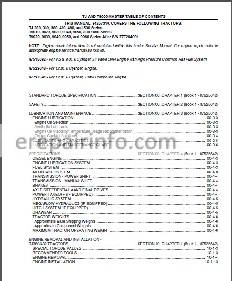
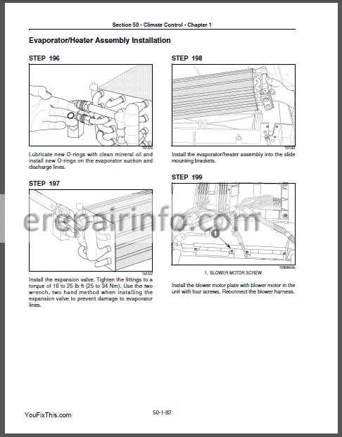
Factory Service Repair Manual For New Holland TJ and T9000 Series Tractors. Tons of illustrations, instructions, diagrams for step by step remove and install, assembly and disassembly, service, inspection, repair, troubleshooting, tune-ups.
Format: PDF
Language: English
Pages: 2993
Bookmarks: Yes
Searchable: Yes
Number: 84257310
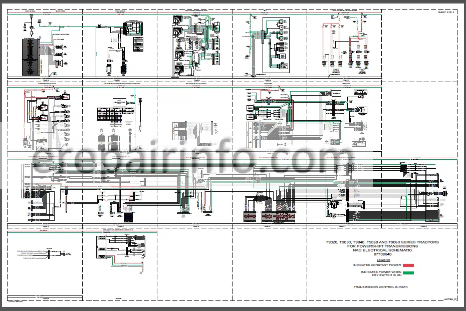
Wiring Diagrams: Yes
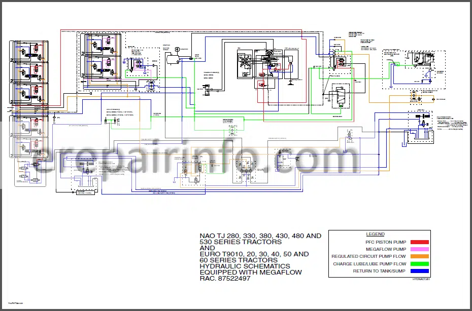
Hydraulic Diagrams: Yes
Model
TJ 280, 330, 380, 430, 480, and 530 Series
T9010, 9020, 9030, 9040, 9050, and 9060 Series
T9020, 9030, 9040, 9050, and 9060 Series After S/N Z7F204001
Contents
- Engine
Special Torque Values
Air Induction System
Air Induction System Description
Air Induction System
Air Filter Elements
Prmary And Secondary Filter Element Removal
Prmary Filter Element Service
Restriction Indicator Switch Removal And Test
Air Cleaner Housing Removal
Aspirator Strata Tube Cleaning
Aspirator Safety Check Valve Removal And Test
Aspirator Safety Valve Installation
Air Cleaner Housing Installation
Restriction Indicator Switch Installation
Secondary And Primary Filter Element Installation
Viscous Pan Drive
Hydraulic Fan Drive
Air To Air Cooler
Air To Air Cooler
A’C Condenser
Hydraulic/Transmission
Oil Cooler
Hydraulic Transmission
Radiator And Cooler
?1? Induction
Primary And Secondary Filter Element
Primary Alter Element
Restriction Indicator Switch
Air Cleaner Housing
Aspirator Strata Tube
Aspirator Safety Check Valve
Aspirator Safety Valve
Air Cleaner Housing
Restriction Indicator Switch
Secondary And Primary Filter Element - Transmission, Drivelines
Drive Coupler
Special Torque
Input (First) Shaft
Pump (Second) Shaft
Master Clutch (Fourth) Shaft
Output (Rfth) Shaft
Counter (Third) Shaft
Cleaning And Inspection
Clutch Pack Clearance And Clutch Pack Travel
Clutch Gear Bearing Preload Test
Pump (Second) Shaft
Master Clutch (Fourth) Shaft
Output (Rfth) Shaft
Counter (Third) Shaft Bearing
Regulator Valve
Lube Regulator Valve
Vaster Dutch Lube Vake
Range Seectcc Valve
Master Clutch Control Valve
Transmission Power Flow
Default Seringa
Helical Out Gears
Rear Drive Line And Carrier Bearing
Pump
Speed Transmission
Master Clutch
Shift Lever Linkage
Drive Coupler
Pressure Testing
Transmission Pressure Test Port
Testing The Lubrication Pressure
Transmission Serial Number
Transmission Lubrication Circuit
Transmission Oil Flow Chart
Transmission Power Flow
Starting In A Forward Speed
Starting In A Reverse Speed
Troubleshooting Guide
Neutral Safety Switch
Transmission Speed Sensor
Transmission
Shift Lever Seal
Input Shaft Assembly
Pump Shaft Assembly
Speed Shaft
Center Shaft
Range Shaft Disassembly
Cleaning Inspection And Solenoid Valve
Regulator Valve
Range Selector Valve
Power Take Off - PTO
Pto Lubrication
Pto Control
Pto Control Switch
To Operate The Pto
To Stop The Pto
Pto Electrical Circuit
Pto Switch In The Off Position
Pto Switch In The On Position
Diode Suppressed Pto Coil
Neutral Start Feature
Pto Valve
Operational Modes
Pto Control Valve Operation
Pto Clutch Disengaged
Pto Modulated Engagement
Pto Fully Engaged
Pto Clutch Drive
Pto Clutch
Pto Brake
Pto Drop Box And Clutch
Engine Rpm Speed Circuit
Pto System Troubleshooting
Pto Will Not Engage
Pto Will Not Disengage
Pto Drive Unit Disassembly
Pto Drive Unit Assembly (Exploded View)
Pto Clutch And Brake Assembly (Exploded View) ™
Pto Drive Unit Assembly
Transfer Case
Pto Dropbox
Exploded View Pto Dropbox
Pto Drive Une Hanger Bearing
Hanger Bearing
Pto Valve - Brakes
Axle Pump
Axle Cooling Filter
Axle Lube Solenoid Valve
Pressure/Lube Control Valve
Brake Lubrication And Jet Pump
Pressure/Lube Control Valve
Regulated Pressure Spool
Park /Valve
Park Brake Applied
Park Brake Released
Tow Valve
Brake Circuit Components
Brake Pedal
Brake Control Valve
Brake Clutch Pack
Axle Brake Cylinders
Hydraulic Brake Control
General Description
Brake Valve
Service Brake Circuit
Emergency Braking - Hydraulic Systems, 3PT
Circuit Diagrams
Symbol Systems
Using Schematic Symbols
Reservoirs
Lines, Tubes And Hoses
Crossing Or Joining Lines
Pump Symbols
Hydraulic Motor Symbols
Cylinder Symbols
Pressure Control Symbols
Normally Closed
Normally Open
Relief Valve
Pressure Reducing Valve
Sequence Valve
Directional Control Symbols
Simplified Symbols
One Way Valve
By Pass Valve
Composite Symbols
One Way Valves
Two Position Valves
Three Position Valves
Actuating Controls
Flow Control Symbols
Restrictors
Accessories - Drawbar, Towing and Ballasting
Special Torque Values
Special Tools
Drawbar Removal
Drawbar Installation - Frames
Separating The Front And Rear Frames
Bottom Hinge Bearing Replacement
Connecting Link Front Bushing
Connecting Unk
Connecting The Front And Rear Frames - Steering
Tilt Steering Column
Steering Wheel
Transmission Shift Lever
Center Console Cover R
Transmission Shift
Steering Wheel
Steering Column
Tit Steering Column Release Cable
Clutch And Brake Pedal
Deceleration Switch
Clutch Potentiometer
Differential Lock Brake Switch
Hvac Plenum/ Actuator Motor And Louver
Transmission Shift Lever
Steering Hand Pump
Steering Tube Unes
Steering Priori Ty/Control Valve
Steering Hand Pump - Axles, Wheels
Front Axle
Rear Axle
Axle Final Drive
Final Drive
Planetary Carrier
Final Drive Housing
Front Cover
Rm Side Brake Carrier
Brake Carrlefvbearing Support
Rm Brake Carrier Assembly
Differential
Differential Case
Lh Differential Bearing Carrier
Adjusting Bevel Pinion Gear
Setting Differential Carrier Bearing Preload
Setting Ring»P1N1On Gear Backlash
Rh Bearing Carrier brake Support
Front Cover
Final Drive
Axle Lubrication Circuit
Axle Lubrication - Climate Control
Air Conditioner System Refrigerant
Recovering Pure 134A Refrigerant
Recovering Contaminated Refrigerant
Recovery Process
Air Conditioner System Evacuation And Recharging
Air Conditioning Temperature/Pressure Chart
Leak Detection
Electronic Testing
Fluorescent Leak Detection
Fluorescent Dye Injection
Recovery Station Dye Injector Tool With A System In A Vacuum
Recovery Station Dye Injector Tool With A Charged System
Quick And Easy Dye Injector Tool With A Charged System
Compressor Oil Port
Sp-20 Pag Oil Return Bottle
Fluorescent Leak Testing
A’c System Flushing Procedure
Required Tools
Precautions
Component Flushing Procedure With Power Flush
Complete Circuit Flushing Procedure With Power Flush
Back Flushing The Thermal Expansion Valve Or Refrigerant Line
Post Flushing Procedures
Flushing Solvent Disposal
A’c System Components
Cab Hvac Box Components – Automatic Temperature Control
Ac Compressor Clutch
A/C Compressor
Oil Level Check Or Adjustment
Injection Method
Dipstick Method
Thermal Expansion Valve
Condenser And Receiver-Drier
Accessing The Hvac Box
Evaporator Temperature Sensor Location
Blower Motor Replacement
Heater Control Valve Replacement
Evaporator Heater
Post Replacement Procedures
Evaporator/Heater Assembly Sealing And Cleaning
Blower And Evaporator Reference Illustration
Controller Blower Driver & Standard A-‘c Controller Replacement
Accessing And Replacing The Mode Door Motor
Cab Intake Air Filter Service
Cab Recirculation Air Filter Service
Cab Pressurization Test
Cab Pressurizer Motor Replacement
Viscous Fan Drive - Electrical System
Fuse And Relay
Deluxe Cab Powershift Transmission
Deluxe Cab Speed Transmission
Instrumentation And Controls
Aux1Uary Auto Mode Switch (If Equipped)
Connector And Component Location
Electrical Systems Schematics And Diagnostic
Audio System Circuit Operation
Charging System
Power Mirror System
Power Seat System
Starting System
Wiper/ Washer SystemFuse And Relay
Deluxe Cab Powershift Transmission
Deluxe Cab Speed Transmission
Instrumentation And Controls
Aux1Uary Auto Mode Switch (If Equipped)
Connector And Component Location
Electrical Systems Schematics And Diagnostic
Audio System Circuit Operation
Charging System
Power Mirror System
Power Seat System
Starting System
Wiper/ Washer System - Cab, Hood, Seat
Cab Top
What you get
You will receive PDF file with high-quality manual on your email immediately after the payment.



Reviews
There are no reviews yet