Repair Manual For New Holland TR86 TR87 TR88 Combines. Illustrations, instructions, diagrams for step by step remove and install, assembly and disassembly, service, inspection, repair, troubleshooting, tune-up.
Format: PDF
Language: English
Pages: 1900
Bookmarks: Yes
Searchable: Yes
Wiring Diagrams: Yes
Hydraulic Diagrams: Yes
Model
New Holland TR86, TR87, TR88
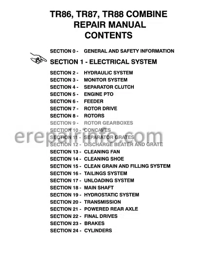
Contents
- – Electrical System
Activating The Automatic Head Height Control Circuit
Air Conditioner Compressor Clutch Control Circuit
Air Conditioner Compressor Clutch Control Circuit
Air Conditioner Compressor Clutch Troubleshooting
Air Conditioner Compressor Clutch Troubleshooting
Air Conditioning Circuit
Air Conditioning Electrical System
Automatic Head Height Control Circuit
Automatic Head Height Lower Circuit
Automatic Head Height Raise Circuit
Automatic Head Tilt (Lateral Float) Circuit
Circuit Breakers
Cleaning Fan, Feeder, And Rotor Variable
Speed Control Circuit
Cleaning Fan Speed Decrease Circuit
Cleaning Fan Speed Increase Circuit
Coil Spark Suppression Diode Test
Coil Test Procedure
Cold Start Circuit
Cold Start System
Cold Start System Troubleshooting
Diode Chart
Diode Test Procedure
Diodes
Disengaging The Automatic Head Height
Circuit
Electrical System Components
Electrical System Introduction
Electrical Terms
Electrohydraulic CircuitsTroubleshooting
Electrohydraulic Electrical System
Electrohydraulic Function
Electrohydraulic Stack Valve Main Power Circuit
Electronic Stone Trap Circuit
Electronic Stone Trap Detection Circuit
Electronic Stone Trap Electrical System
Engine Electrical System
Engine Electrical System Troubleshooting
Engine Run Circuit
Engine Start (Cranking) Circuit
Fan (Pressurizer) Circuit
Fan (Pressurizer) Circuit Operation
Fan Speed Control Circuit
Fan Speed Control Circuit Troubleshooting
Feeder, Rotor, And Cleaning Fan Variable Speed Control Circuit
Feeder Reverser Circuit
Feeder Speed Decrease Circuit
Feeder Speed Increase Circuit
Fuel Solenoid Run Circuit
Fuses
Hazard And Turn Signal Lights
Hazard Light Circuit
Head Control Circuit
Head Tilt Circuit (Manual Control)
Hydraulic Reel Speed Control Circuit
IntroductionElectrical System
Left Turn Signal Circuit
Light Electrical Systems
Main Power Circuit Air Conditioning Circuit
Main Power Circuit Automatic Head Height Control Circuit
Main Power Circuit
Lights 1C
Master Solenoid Relay Activated Circuit
Momentary Switches
Powered Reel Axle Circuit
Reel ForeAft Circuit
Reel Lift Circuit
Relay Chart
Relay Test Procedure
Relays
Right Turn Signal Circuit
Road Lights
Road Lights Activated Circuit
Rotor, Cleaning Fan And Feeder Variable
Speed Control Circuit
Rotor Speed Decrease Circuit
Rotor Speed Increase Circuit
Solenoid Activation Chart
Solenoid Coils
Solenoid Operation
Stone Door Warning Circuit Activated
Stone Door Warning Circuit Not Activated1
Switch Power CircuitRotor Cleaning Fan And
Feeder Variable Speed Control Circuit1
Troubleshooting Air Conditioner Compressor
Troubleshooting Air Conditioning System
Troubleshooting Automatic Head Height
Control Circuit
Troubleshooting Automatic Head Tilt Circuit
Troubleshooting Cold Start System
Troubleshooting Electrohydraulic Circuits
Troubleshooting Electrohydraulic Stack Valve Main Power Circuit
Troubleshooting Electrohydraulic Stack Valve Main Power Circuit
Troubleshooting Electronic Stone Trap Circuit
Troubleshooting Engine Run Circuit
Troubleshooting Engine Start Circuit
Troubleshooting Fan Speed Control Circuit
Troubleshooting Feeder Reverser Circuit
Troubleshooting Hazard And Turn Signal
Troubleshooting Head Control Circuit
Troubleshooting Head Tilt Circuit (Manual)
Troubleshooting Light Electrical Systems
Troubleshooting Powered Rear Axle
Troubleshooting Reel ForeAft Circuit
Troubleshooting Reel Lift
Troubleshooting Hydraulic Reel Speed Control Circuit
Troubleshooting Road Lights
Troubleshooting Rotor, Cleaning Fan And Feeder Variable Speed Control Circuit
Troubleshooting Unloading Auger Swing Circuit
Troubleshooting Work Lights
Turn Signal And Hazard Lights
Unloading Auger Swing Circuit
Variable Speed Control Electrical System
Wiring Diagrams
Work Lights Circuit
Work Lights Activated Circuit - – Hydraulic System
Electrohydraulic Stack Valve Operation
Electrohydraulic Stack Valve Service
Hydraulic Pump
Steering Control
Accumulator
Hydraulic System Troubleshooting
Reel Drive Hydraulic System
Unloading Auger Drive And Head Drive Control Valve (Tr O N Ly ) - – Monitor System
Grain Loss Monitor Circuits
Operation
Troubleshooting
Ground Speed Calibration
Instrument Bar Circuit
Battery Charge Level, Park Brake, And
Drives Engaged Alarm Systems
Drives Engaged Alarm Circuits
Engine And Hydraulic System
Alarm Lights
Gauge Checks
Gauge Circuits
Hour Meter
Instrument Bar Power
Introduction
Tr And Tr Drives Engaged
Alarm System
Tr Drives Engaged Alarm System
Troubleshooting
Monitor Circuit - – Separator Clutch
Adjusting The Separator Clutch
Assembling The Separator Clutch
Bearing S E T
Disassembling The Separator Clutch
Installing The Main Sheave
Installing The Separator Clutch
Introduction
Labor Guide
Main Sheave
Removing The Main Sheave
Removing The Separator Clutch
Separator Clutch
Separator Clutch Layout
Special Tool Layout - – Engine Pto
Engine Pto Shaft
Bell Housing
Removing Th E Bell Housing
Disassembling The Bell Housing
Bell Housing Parts
Inspecting The Bell Housing
Assembling The Bell Housing
Installing The Bell Housing
Bell Housing
Removing The Bell Housing
Disassembling The Bell Housing
Bell Housing Parts - – Feeder
Adjusting The Feeder Slip Clutch
Assembling And Installing The Reverser Gearbox
Assembling The Reverser Motor
Cradle And Feeder Face Plate
Disassembling The Front Drum
Disassembling The Reverser Motor
Electronic Stone Trap
Feeder Face Plate And Cradle
Feeder Floor
Feeder Maintenance
Feeder Slip Clutch
Front Drum
Housing Bearing Replacement Procedures
Installing The Front Drum
Installing The Intermediate Idler Sheave Variable Speed
Installing The Stone Roll
Installing The Upper Pivot Shaft
Installing The Upper Pivot Shaft Idler Fixed Speed
Installing The Upper Pivot Shaft Idler Variable Speed
Intermediate Idler SheaveVariable Speed
Introduction
Labor Guide
Main Drive Belt
Removing And Disassembling The Reverser Gearbox
Removing And Installing The Cradle
Removing And Installing The Feeder Face Plate
Removing And Installing The Feeder Floor
Removing And Installing The Feeder Slip Clutch
Removing And Installing The Header Jackshaft Drive Belt
Removing And Installing The Main Drive Belt
Removing And Installing The Variable Speed M
Removing The Feeder From The Combine
Removing The Front Drum
Removing The Intermediate Idler Sheave Variable Speed
Removing The Reverser Motor
Removing The Stone Roll
Removing The Upper Pivot Shaft
Removing The Upper Pivot Shaft Idler
Reverse Gearbox
Reverser Motor
Right Side Drives
Stone Roll
Transducer Replacement
Upper Pivot Shaft
Upper Pivot Shaft Idler
Variable Speed Motor
Variable Speed Screw - – Rotor Drive
Adjusting the rotor speed
Assembling the speed screw
Assembling the torque sensing drive
Disassembling the speed screw
Disassembling the torque sensing drive
Installing the lower variator sheave
Installing the rotor drive belt
Installing the rotor speed electric motor
Installing the speed screw
Installing the torque sensing drive
Introduction
Labor guide
Lower variator sheave
Removing the lower variator sheave
Removing the rotor drive belt
Removing the rotor drive speed screw
Removing the rotor speed electric motor
Removing the torque sensing drive
Rotor drive
Rotor drive belt
Rotor drive speed screw
Rotor speed electric motor
Torque sensing drive - – Rotors
Assembling The Rotor
Balancing The Rotor
Disassembling Therotor
Installing The Rotors
Labor Guide
Parts Inspection
Removing The Rotors
Assembling The Rotor
Balancing The Rotor
Disassembling The Rotor
Installing The Rotors
Labor Guide
Parts Inspection
Removing The Rotors
Replacing The Rasp Bar Mount - – Rotor Gearboxes
Rotor Gearboxes
Removing The Rotor Gearboxes
Installing The Rotor Gearboxes
Special Tools Needed
Single Speed Rotor Gearbox
Left Rotor Gearbox
Disassembling The Left Rotor Gearbox
Left Rotor Gearbox Parts
Inspecting The Left Rotor Gearbox
Assembling The Left Rotor Gearbox
Right Rotor Gearbox
Disassembling The Right Rotor Gearbox
Right Rotor Gearbox Parts
Inspecting The Right Rotor Gearbox
Assembling The Right Rotor Gearbox
Labor Guide
Two Speed Rotor Gearbox
Left Rotor Gearbox
Disassembling The Left Rotor Gearbox
Left Rotor Gearbox Parts
Inspecting The Left Rotor Gearbox
Assembling The Left Rotor Gearbox
Right Rotor Gearbox
Disassembling The Right Rotor Gearbox
Right Rotor Gearbox Parts
Inspecting The Right Rotor Gearbox
Assembling The Right Rotor Gearbox - – Concaves
Removing And Installing The Concave Extensions
Removing The Main Concaves
Installing The Main Concaves
Adjusting The Concaves
Initial Settings
Concave Leveling
Concave Centering
Final Adjustments
Removing And Installing The Concave Extensions
Removing And Installing The Main Concaves
Adjusting The Concaves
Initial Settings
Concave Leveling
Concave Centering
Final Adjustments
Concave H Frame
Removing The H Frame
Installing The H Frame - – Separator Grates
Removing The Separator Grates
Installing The Separator Grates - – Discharge Beater And Grate
Discharge Beater
Discharge Beater Grate
Installing The Discharge Beater
Installing The Discharge Beater Grate
Introduction
Labor Guide
Removing The Discharge Beater
Removing The Discharge Beater Grat - – Cleaning Fan
Shielding
Removing The Fan Bottom Shield
Installing The Fan Bottom Shield
Removing And Installing The Auger Mud Shield
Cleaning Fan Drive
Removing The Cleaning Fan Drive Beltt
Installing The Cleaning Fan Drive Belt
Removing The Cleaning Fan Driven Sheave
Installing The Cleaning Fan Driven Sheave
Variable Speed Motor
Removing And Installing The Variable Speed Motor
Cleaning Fan Shaft
Removing The Cleaning Fan Shaft
Installing The Cleaning Fan S Haft
Cleaning Fan Housing
Removing The Cleaning Fan Housing
Disassembling The Cleaning Fan Housing
Assembling The Cleaning Fan Housing
Installing The Cleaning Fan Housing - – Cleaning Shoe
Chaffer And Cleaning Sheave
Chaffer
Cleaning Sieve
Disassembling The Shoe Drive A Rm Grain Pan
Installing The Chaffer
Installing The Cleaning Sieve
Installing The Lower Shoe
Installing The Shoe Eccentric Shaft
Installing The Upper Shoe
Introduction
Labor Guide
Lower Shoe
Removing The Chaffer
Removing The Cleaning Sieve
Removing The Lower Shoe
Removing The Shoe Eccentric Shaft
Removing The Upper Shoe
Shoe Bushing Tightening Sequence
Shoe Drive Arm, Disassembling
Shoe Eccentric Shaft
Upper Shoe - – Clean Grain And Filling System
BubbleUp Auger
Cross Auger
Elevator
Elevator Chain
Gearbox Assembly
Gearbox Disassembly
Gearbox Parts Layout
Installing The BubbleUp Auger
Installing The BubbleUp Auger Gearbox
Installing The Cross Auger
Installing The Elevator
Installing The Slip Clutch
Introduction
Labor Guide
Removing And Installing The Elevator Chain
Removing The BubbleUp Auger
Removing The BubbleUp Auger Gearbox
Removing The Cross Auger
Removing The Elevator
Removing The Slip Clutch - – Tailings System
Lower Cross Auger
Upper Cross Auger
Elevator - – Unloading System
Cross Auger
Drive Belt
Telescoping Transition Auger
Telescoping Transition Auger
Unloader Jackshaft
Unloading Auger And Tube - – Mainshaft
Left Bearing
Main Shaft
Right Bearing - – Hydrostatic System
Alternate Neutral Adjustment
Assembling The Charge PumpStyle
Assembling The Hydrostatic Motor
Assembling The Hydrostatic Pump
Assembling The Internal Pressure Override
Case Pressure
Charge Pressure
Charge Pump Circuit
Charge Relief Valve
Check Valves
Cooling Circuit
Disassembling The Charge PumpStyle
Disassembling The Hydrostatic MotorE
Disassembling The Hydrostatic Pump D
Disassembling The Internal Pressure Override
Discoloration
Displacement Control Valve
Forward
Grooves
High Pressure
Hydrostatic Diagrams
Hydrostatic Motor Service Major Repairs
Hydrostatic Pressure Override Control
Hydrostatic Surge Pressure Relief Valves
Inspecting The Charge Pump
Inspecting The Hydrostatic Motor
Installing The Charge Pump
Installing The Control Valve
Installing The Cylinder Assembly
Installing The Hydrostatic Motor
Installing The Hydrostatic Pump
Installing The Shaft Seal
Internal Pressure Override
Introduction
Labor Guide
Main Pump And Motor Circuit
Manifold
Metric Conversions
Neutral
Normal Neutral Adjustment
Oil Requirements
Operation
Parts Evaluation
Pressure Checks
Relief Valve Replacement
Removing The Charge Pump
Removing The Control Valve
Removing The Hydrostatic Motor
Removing The Hydrostatic Pump
Removing The Shaft Seal
Reverse
Sauer/Sundstrand Service Centers
Scratches
Serial Number Identification
Shaft Seal E,
Shuttle Valve Replacement
Startup Procedure
System Function
Terms Used In Failure Analysis
Torque Values
Troubleshooting Charge Pump
Troubleshooting Hydrostatic Motor
Adjusting Charge Pressure Relief Valve
Adjusting The Speed Control Linkage
Assembling The Motor
Assembling The Pump
Case Pressure F
Charge Pressure
Charge Pump Circuit
Control Valve
Controls
Disassembling The Motor
Disassembling The Pump
Gauge Information
High Pressure
Inspecting The Control Valve
Inspecting The Motor
Inspecting The Pump
Installing The Charge Pressure Relief Valve
Installing The Charge Pump
Installing The Control Valve
Installing The Loop Flushing Valve
Installing The Motor
Installing The MultiFunction Valve
Installing The Pump
Installing The Shaft (Pump And Motor)
Installing The Shaft Seal
Introduction
Labor Guide (Minor Repairs)
Main Pump And Motor Circuit
Major Repairs
Metric Conversions
Minor Repairs
Motor Repairs
Multi Function Valve
Multi Function Value Adjustment
Operation
Pressure Checks
Pump Repairs
Removing The Charge Pressure Relief Valve
Removing The Charge Pump
Removing The Control Valve
Removing The Loop Flushing Valve
Removing The Motor
Removing The multifunction Valve Cartridge
Removing The Pump
Removing The Shaft (Pump And Motor)
Removing The Shaft Seal
Sauer/Sundstrand Service Centers
Serial Number Identification
Serial Number Plate
Special Tools
Startup Procedures
Terms Used In Failure Analysis
Torque specifications
Troubleshooting (Minor Repairs) - – Transmission
Disassembling The Transmission
Removing The Transmission
Removing The Shifter Fork
Disassembling The Input Shaft
Disassembling The Counter Shaft
Disassembling The Pinion Shaft
Disassembling The Brake Assembly
Removing The Differential Half Shafts
Disassembling The Differential
Differential Parts
Assembling The Transmission
Assembling The Differential
Installing The Differential
Assembling The Differential Half Shafts
Brake And Differential Parts
Assembling The Brakes
Transmission Parts
Assembling The Pinion Shaft
Assembling The Counter Shaft
Assembling The Input Shaft
Assembling The Shifter Forks
Shimming The Pinion Shaft
Shimming The Counter Shaft
Shimming The Input Shaft - – Powered Rear Axle
Control Valve Removal
Disassembling The Control Valve
Assembling The Control Valve
Control Valve Installation
Motor And Torque Hub Removal And Installation
Startup Procedures
Oil Requirements
Labor Guide
Powered Rear Axle Motors
Operation
Disassembling The Motor
Inspecting The Motor Parts
Assembling The Motor
Labor Guide
Powered Rear Axle Torque Hubs
Introduction
Tools Needed
Disassembling The Main Hub
Disassembling The Carrier
Disassembling The Cover
Inspection
Assembling The Main Hub
Assembling The Carrier
Assembling The Cover
Assembling The Hub/Spindle
Assembling The Main Hub
Bolt Torque And Tightening Sequence - – Final Drives
Final Drive
Disassembling The Final Drive
Disassembling The Output Shaft
Output Shaft Parts
Disassembling The Input Shaft
Input Shaft Parts
Final Drive Parts
Reassembling The Final Drive
Assembling The Input Shaft
Assembling The Output Shaft
Labor Guide
Disassembling The Final Drive
Disassembling The Output Shaft
Output Shaft Parts
Disassembling The Input Shaft
Input Shaft Parts
Inspection
Final Drive Parts
Reassembling The Final Drive
Assembling The Input Shaft
Assembling The Output Shaf - – Brakes
Master Cylinder
Slave Cylinder
Bleeding The Hydraulic Brake System
Disc Brake - – Cylinders
Contents
Head Drive And Unloading Auger
Drive Cylinder
Removing The Head Drive Cylinder
Removing The Unloading Auger
Head Lift Cylinders
Power Steering Cylinders
Toe-In Adjustment
Reel Fore-Aft Cylinders
Reel Lift Cylinders
Adjusting Reel Height
Leveling The Reel
Terrain Tracer™ (Lateral Float) Cylinders
Installing The Cylinders
What you get
You will receive PDF file with high-quality manual on your email immediately after the payment.

Reviews
There are no reviews yet