Factory Workshop Manual For 4000 Series 4006-23 TAG1A TAG2A TAG3A engines. Tons of illustrations, instructions, diagrams for step by step remove and install, assembly and disassembly, service, inspection, repair, troubleshooting, tune-ups.
Format: PDF
Language: English
Pages: 272
Number: TPD1511E
Searchable: Yes
Model
Perkins 4000 Series
4006-23 TAG1A, TAG2A, TAG3A
6 cylinder turbocharged diesel engine for electric power applications
Contents
-GENERAL INFORMATION
Introduction
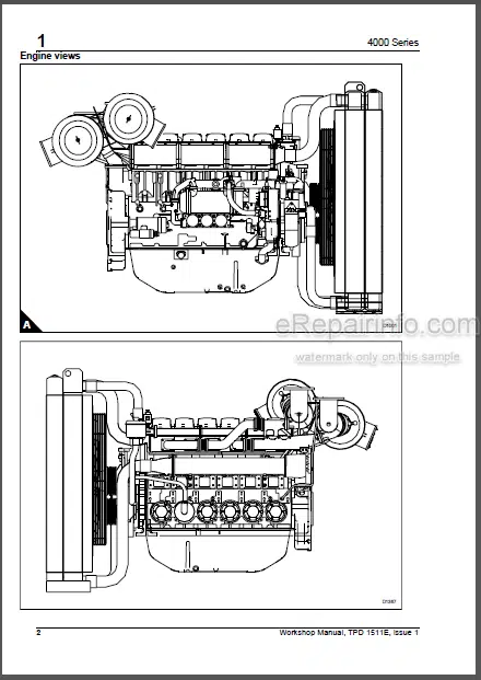
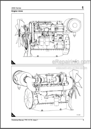
Engine Views
Engine Identification
General Safety Precautions
Viton Seals
Engine Lift Equipment
Power part Recommended Consumable Products
-SPECIFICATIONS
Basic Engine Data
Data And Dimensions
-CYLINDER HEAD ASSEMBLY
General Description
Rocker Box And Valve Gear
Valve Gear
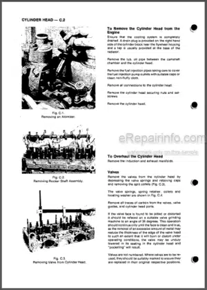
Cylinder Head
Valves And Springs
Valves Seats
Valves Guides
Fuel Injector Bush
Cylinder Head
Manifolds
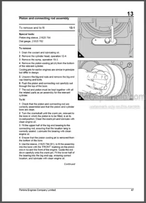
-PISTON AND CONNECTING ROD ASSEMBLIES
General Description
Piston And Connecting Rod
Piston Rings
Piston And Connecting Rod Assembly
Piston And Piston Rings
Connecting Rod
Small End Bush
Piston Cooling Jets
-CRANKSHAFT ASSEMBLY
General Description
Crankshaft Pulley And Adaptor
Crankshaft Vibration Damper Assembly
Crankshaft
-GEARCASE AND DRIVE ASSEMBLY
General Description
Gearcase
Front Oil Seal
Camshaft Gear
Idler Gear
Cam Followers
Camshaft
Crankshaft Gear
Back Plate
-CRANKCASE
General Description
Crankcase
Cylinder Liner
-ENGINE TIMING
-ASPIRATION SYSTEM
General Description
How To Check The Air Restriction Indicator
Air Filter Element
Air Filter And Pipe Connection
Air Filter Bracket
Turbocharger
Air Pipe Connection
Engine Breather
-LUBRICATION SYSTEM
General Description
Filter Canister
Filter Head
Lubricating Oil Sump
Dipstick Tube
Oil Strainer And Suction Pipe
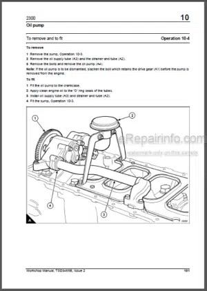
Lubricating Oil Pump
Relief Valve
Fuel Lift Pump Drive Unit
Rotor End Float
Drive Shaft Bearings
-FUEL SYSTEM
General Description
Fuel Filter
Fuel Injector Unit
To Test And Set The Fuel Injector
Fuel Lift Pump
Fuel Control Shaft
-COOLING SYSTEM
Coolant Pipework
Thermostat
Thermostat Housing
Coolant Pump
Fan Guards
Fan
Fan Drive Belts
Fan Drive
Lubricating Oil Cooler
Radiator
-FLYWHEEL AND HOUSING
General Description
Flywheel
Gear Ring
Flywheel Housing
Flywheel Housing Oil Seal
-ELECTRICAL EQUIPMENT
General Description
Alternator
Starter Motor
The Air Starter Motor System
Stop Solenoid
Digital Electronic Governor
Description Of System
Block Diagram Of The Governor System
Magnetic Pick-Up
Specification Of Governor System
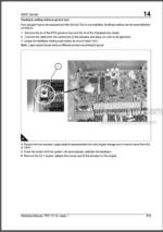
Feedback Setting
Configuration
External Speed Control Input
Changing The Governor Configuration
Single/Parallel Generator (Non Heinzmann Load Sharing)
Single/Parallel Generator With Droop
Parallel Generator Heinzmann (Syg02/Lmg10-01)
Parallel Generator Heinzmann Digital Theseus
Parallel Generator Variable Speed In Droop Range
Other Settings
Pid Parameters
Pid Maps
Speed Ramps
Sectional Speed Ramp
External Connections – Control Box Connector
Alternative Connections For Speed Setting Inputs
Wiring Detail, Digital Control Box In Ip Enclosure – Production Engines
Fault Tracing
Error Codes
Low Oil High Water Temperature Switch
Switch Connections
Switch Setting
-AUXILIARY EQUIPMENT
-SPECIAL TOOLS
List Of Special Tools
What you get
You will receive PDF file with high-quality manual on your email immediately after the payment.



Reviews
There are no reviews yet