Factory Service Manual And Troubleshooting Guide For Sperry New Holland 1400, 1500 Combine. Manual Contains Illustrations, Instructions, Diagrams For Step By Step Remove And Install, Assembly And Disassembly, Service, Inspection, Repair, Troubleshooting, Tune-Ups.
Format: PDF
Language: English
Quantity of Manuals: 2
Pages: 8; 190
Number: 40481400; 40481300
Bookmarks: Yes
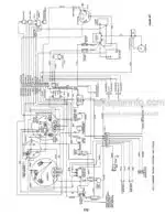
Wiring Diagrams: Yes
Model
New Holland Combine
1400
1500
Contents
-CYLINDER AND CONCAVE AREA
Removal and Installation of the Stone Trap and Concave
Disassembly and Assembly of the Concave Control Lever
Adjustment of the Concave
Removal and Installation of the Cylinder
Replacement of Cylinder Rasp Bars
Adjustment of the Cylinder Drive Belt
Replacement of the Concave Rake
-BEATER AREA
-INTERMEDIATE SHAFT AREA
Replacement of the Intermediate Shaft L H Bearing — Machines 1971-1972
Replacement of the Intermediate Shaft R H Bearing — Machines 1971-1972
Replacement of an Intermediate Bearing in the Bearing Housing — Machines 1971-1972
Replacement of the Intermediate Shaft — Machines 1971-1972
Replacement of the Intermediate Shaft L H Bearing — Machines from 1973 On
Replacement of the Intermediate Shaft R H Bearing — Machines from 1973 On
Replacement of a Bearing in the Bearing Housing — Machines from 1973 On
Replacement of the Intermediate Shaft — Machines from 1973 On Replacement of the Variator Sheave Bushings
Disassembly and Assembly of the Threshing Mechanism Linkage Adjustment of the Banded V-Belt Tension
Replacement of the Threshing Mechanism Clutching Lever
-CYLINDER VARIABLE DRIVE AREA
Removal of the Cylinder Variator Drive Belt
Installation of the Cylinder Variator Drive Belt
Adjustment of the Cylinder Variator Drive
Disassembly of the Cylinder Variable Speed Control Mechanism
-STRAW WALKER AREA
Disassembly of the Straw Walkers and Shafts on
1400 and 1500 Combines
Replacement of a Straw Walker Bearing — 1500
Mounting of the Straw Walker Shafts — 1500
Alignment and Adjustment of the Straw Walker Shafts — 1500
Replacement, Mounting, and Adjustment of Straw Walker
Bearings and Shafts — 1400
Mounting of the Walkers — 1500-1400
Retarding Curtain — 1500-1400
-CLEANING SHOE AND ECCENTRIC DRIVE AREA
-CLEANING FAN AND VARIABLE DRIVE AREA
Disassembly of the Cleaning Fan
Assembly of the Cleaning Fan
Replacement of the Horizontal Adjustable Wind Boards
Adjustment of the Wind Boards and Wind Deflectors — 1500
Adjustment of the Wind Boards and Wind Deflectors — 1400
Disassembly and Installation of the Cleaning Fan
Variable Drive Lower Sheave Assembly
Disassembly and Assembly of the Cleaning Fan Variable Drive
Adjustment of the Cleaning Fan Variable Drive
-GRAIN PAN AND SHAKER SHOE AREA
Removal and Installation of the Upper Section of the Cleaning Shoe
Removal and Installation of the Lower Section of the Cleaning Shoe
Removal and Installation of the Grain Pan
Adjustment of the Cleaning Shoe and the Grain Pan
-GRAIN AND TAILINGS ELEVATOR AREA
Removal and Installation of the Tailings Elevator Chain
Removal and Installation of the Tailings Elevator
Disassembly and Reassembly of the Tailings Elevator Top Shaft
Disassembly and Reassembly of the Tailings Elevator Drive Shaft
Removal and Installation of the Clean Grain Elevator Chain
Disassembly and Reassembly of the Clean Grain Elevator Top Shaft
Removal and Installation of the Grain Elevator
Disassembly and Reassembly of the Grain or Tailings Auger
Disassembly and Reassembly of the Tailings Top Cross Auger
Disassembly and Reassembly of the Grain Tank Filling Auger System
Disassembly of the Filling Auger Gear Box
Reassembly of the Filling Auger Gear Box
-GRAIN TANK AREA
Disassembly, Assembly and Adjustment of Unloading Auger — Machines from 1973 On
Replacement of the Bevel Gears and Bearings in the Angle Drive of the Unloading Auger — Machines from 1973 On
Disassembly and Assembly of the Angle Drive Gearbox
Disassembly and Assembly of the Drive Gear Box for the Unloading Auger
Replacement of the Drive Bevel Gear
Replacement of the Bearings in the Lower Gear Box Half
Replacement of the Grain Tank Cross Auger Bearings
Replacement of the Grain Tank Cross Auger
Disassembly and Reassembly of the Unloading Auger Clutching Linkage
Disassembly of the Clutching Lever on the Operator’s Platform
-STEERING AND REAR AXLE AREA
Replacement of the Universal Joints on the Steering Column
Replacement of the Steering Column Bushings
Replacement of the Steering Column Bearings
Disassembly and Assembly of a Spindle and the Spindle Bushings
Toe-In Adjustment
Replacement of the Pivot Shaft Bushings
Adjustment of the Steering Cylinder
Bleeding of the Hydraulic Steering System
Changing the Adjustable Steering Axle Width
-CLUTCH AND TRANSMISSION AREA
Disassembly, Assembly and Adjustment of the Clutch on a 1500 Combine
Disassembly, Assembly and Adjustment of the Clutch on a 1400 Combine
Adjustment of the Clutch Pedal and Linkage
Replacement of the Clutch Housing Bearings
Replacement of the Drive Shaft Seal
Disassembly and Assembly of the Differential and Gears
Replacement of the Locking Block and the Shifter Shaft Bushings
Removal and Re-installation of the Transmission Gears
Re-installing the Gears in the Transmission
Replacement of a Drive Shaft Housing
Replacement of a Wheel Hub and Bearings
Replacement of a Drive Shaft and Bearings
Traction Wheels and Tires
Replacement of the Gear Shift Mechanism
-BRAKES AND PARKING BRAKE AREA
Parking Brake
Disassembly and Assembly of the Parking Brake System
Removal and Re-installation of Parking Brake Handle on Driver’s Platform
Disassembly and Assembly of Brake Discs
Disassembly and Assembly of Brake System Hydraulic Components
Brake Adjustment
Bleeding the Brake System
Removal and Installation of Brake Pedals
-GROUND SPEED VARI-DRIVE AREA
Removal of Sheave Fork
Disassembly of the Variator Sheave Assembly
Assembly of the Variator Sheave Assembly
Balancing of the Vari-Drive Sheave Assembly
Installing the Sheave Fork
Variator Adjustments
-HYDRAULIC SYSTEM
Good Assembly Practices
Disassembly and Reassembly of the Oil Reservoir and Filter
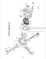
Disassembly and Reassembly of the Hydraulic Pump
Disassembly and Reassembly of the Steering Hand Pump
Disassembly and Reassembly of the 3-Spool Control Valve
Disassembly and Reassembly of the 2-Spool Control Valve
Adjustment of the 3-Spool Valve Controls
Adjustment of the 2-Spool Valve Controls
Disassembly and Reassembly of Combine Hydraulic Cylinders
General Hydraulic Service
Hydrostatic Drive Service
-ELECTRICAL SYSTEM
Battery
Charging System
Console Instruments
Wiring Diagrams
-SPECIAL TOOLS FOR SERVICING MODEL 1400 AND 1500 COMBINES
-ENGINE AREA
What you get
You will receive PDF file with high-quality manual on your email immediately after the payment.



Reviews
There are no reviews yet