Factory Service Repair Manual For Terex PT-70 PT-80 Rubber Track Loader. Tons of illustrations, instructions, diagrams for step by step remove and install, assembly and disassembly, service, inspection, repair, troubleshooting, tune-ups.
Format: PDF
Language: English
Pages: 141
Bookmarks: Yes
Searchable: Yes
Hydraulic Diagrams: Yes
Model
Terex PT70, PT80
Contents
- – Product Safety
Chapter Overview
Safety Messages
Information Messages
Basic Precautions
Safety Labels
Protective Equipment
Entering and Exiting
Lifting
Hot Fluids and Components
Corrosion Inhibitor
Batteries
Pressurized Items
Repair
Attachments
Asbestos Information
Machine Labels and Decals
Product Identification Number
Safety Labels - – Technical Specifications
Specifications
Engine
Transmission
Drive Pumps
Charge Pump
Drive Motors
Pilot Controls
Auxiliary Pump
Lift Arm Control Valve
Oil Cooler
Critical Torque Specifications
Cycle Times
Service Tools
Specifications
Engine
Transmission
Drive Pumps
Charge Pump
Drive Motors
Pilot Controls
Auxiliary Pump
Lift Arm Control Valve
Oil Cooler
Critical Torque Specifications
Cycle Times
Service Tools - – Circuit Diagrams
Chapter Overview
Hydraulic Charge Circuit
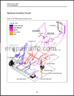
Hydraulic Auxiliary Circuit
Hydraulic Drive Circuit
Lift Arm Control Valve
Hydraulic Pilot Generation Solenoid Block
Electrical Attachment Outlet
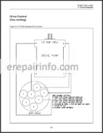
Drive Control (line routing)
Lift Arm Control (line routing) - – Maintenance
Chapter Overview
Personal Safety
LiftArm Brace
Tiltup Cab
Jacking Procedure
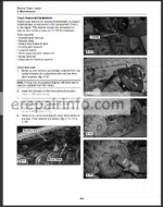
Grease Fittings
Undercarriages
Track Tension
Drive Sprocket Rollers
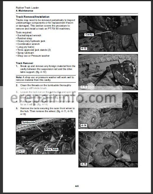
Track Removal
Track Installation
Air Cleaner
Fuel Filter
Water Separator
Accessory Belt Tension
Fan Belt Removal/Installation
A/C Belt Removal/Installation
Engine Oil/FIlter Change
Engine Oil Specifications
Oil Level Check
Hydraulic Fluid/Filter Change
Radiator/Oil Cooler (cleaning)
Engine (cleaning)
Case Drain Filter
Fuse Panel
Maintenance Schedule - – Machine Controls and Instrumentation
Chapter Overview
Machine Controls
Lift Arm Control
Drive Control
Throttle
Instrumentation
Switches
Table of Contents - – Operator Enclosure
Chapter Overview
Personal Safety
Machine Preparation
Removal & Installation
Door Gas Spring
Removal Procedure
Installation Procedure
Pillar Switch Panels
Removal Procedure
Installation Procedure
Side Panels/Gauges
Removal Procedure
Installation Procedure
Seat
Removal Procedure
Installation Procedure
Interior Panel, Rear
Removal Procedure
Installation Procedure - – Chassis and Fuel Tank
Chapter Overview
Personal Safety
Machine Preparation
Removal & Installation
Fuel Sending Unit
Removal Procedure
Installation Procedure
Fuel Tank
Removal Procedure
Installation Procedure
Footwell
Removal Procedure
Installation Procedure
Foot Throttle Assembly
Removal Procedure
Installation Procedure
Hood Assembly
Removal Procedure
Installation Procedure - – Radiator and Oil Cooler
Chapter Overview
Personal Safety
Machine Preparation
Removal & Installation
Fan Guard
Removal Procedure
Installation Procedure
Fan & Shroud
Removal Procedure
Installation Procedure
Radiator/Oil Cooler
Removal
Installation - – Hydraulic Reservoir
Chapter Overview
Personal Safety
Machine Preparation
Removal & Installation
Hydraulic Reservoir
Removal Procedure
Installation Procedure
Suction Screen
Removal Procedure
Installation Procedure - – Lift Arm/Drive Controls
Chapter Overview
Personal Safety
Machine Preparation
Removal & Installation
Joystick
Removal Procedure
Installation Procedure
Lift Arm Float Magnet
Removal
Installation
Lift Arm Control Valve
Removal
Installation - – Hydraulic Pumps/Motors
Chapter Overview
Personal Safety
Machine Preparation
Removal & Installation
Charge Pump
Removal Procedure
Installation Procedure
Auxiliary Pump
Removal Procedure
Installation Procedure
Tandem Drive Pump
Removal Procedure
Installation Procedure
Drive Motor
Removal Procedure
Installation Procedure
Rubber Track Loader
Table of Contents - – Engine
Chapter Overview
Personal Safety
Removal & Installation
Battery
Removal Procedure
Installation Procedure
Exhaust System
Removal Procedure
Installation Procedure
Air Cleaner
Removal Procedure
Installation Procedure
Engine
Removal Procedure
Installation Procedure - – Undercarriage
Chapter Overview
Personal Safety
Machine Preparation
Removal & Installation
Idler Wheel Removal Procedure
Idler Wheel Installation Procedure
Wheel Removal & Installation Procedure
Bogie Wheel & Hub Removal & Service Procedure
Idler Hub
Removal & Service Procedure - – Lift Arm Components
Chapter Overview
Personal Safety
Machine Preparation
Removal & Installation
Lift Cylinder
Removal Procedure
Installation Procedure
Bucket/Tilt Cylinder
Removal Procedure
Installation Procedure
Q/C Block PRV
Removal Procedure
Installation Procedure - – Quick Attach
Chapter Overview
Personal Safety
Machine Preparation
Removal & Installation
Locking Pin
Removal Procedure
Installation Procedure
Pivot Pin
Removal Procedure
Installation Procedure - – Hydraulic Component Service
Chapter Overview
Personal Safety
Hydraulic Cylinder
Lift Arm Control Valve
Drive Motor (motor portion)
Drive Pump (Drive Relief Valves)
Disassembly & Adjustment
PosiPower Relief Valve
Drive Pump
Auxiliary Pump - – Hydraulic Pressure & Flow
Chapter Overview
Personal Safety
Contamination Inspection
Pressure/Flow Test and Troubleshooting
Charge Pressure Check & Adjust
Auxiliary Pressure Check & Adjust
Lift Arm Pressure Check
Drive Pressure Check
Troubleshooting
PosiPower Pressure Check & Adjust
Auxiliary Flow Test
Troubleshooting - – Troubleshooting
Chapter Overview
Personal Safety
Visual Inspection
General Troubleshooting Scenarios
Engine/Machine Troubleshooting - – Lubricant and Fuel Specifications
Chapter Overview
Fluids & Fuel Specifications
What you get
You will receive a PDF file with high-quality manual(s) on your email immediately after the payment.


Reviews
There are no reviews yet