Factory Service Manual For Tigercat Mulcher. Manual Contains Illustrations, Instructions, Diagrams For Step By Step Remove And Install, Assembly And Disassembly, Service, Inspection, Repair, Troubleshooting, Tune-Ups.
Format: PDF
Language: English
Pages: 242
Number: 21325A (january 2004)
Bookmarks
Searchable
Wiring Diagrams
Hydraulic Diagrams
Model
Tigercat Mulcher
M724D
Contents
INTRODUCTION
S.A.E. STANDARDS
NON-APPROVED FIELD PRODUCT CHANGES
-SAFETY
Articulation Lock Bar
Battery Disconnect Switch
Boom Lift Lock
Engine Access Panels
Exhaust Fumes
Feller Buncher Operation Safety
Fire Prevention
First Aid
Fluid Leaks
Hazard Zone
Hydraulic Pressure Hazard
Loose Clothing Hazard
Mulching Operation Safety
Parking The Machine
Protective Clothing
Safety Interlock Switches On Cab Doors
Safety Precautions, General
Safety Precautions, Operating
Safety Precautions, Servicing
Safety Symbols
Signal Words
-USING HIGH SPEED DISC SAWS SAFELY
Comments And Instructions
Dangers
Forward
High Angle Wrist Rotation Capability
Saw Head Don’ts
Type Of Housing Makes A Difference
-LUBRICATION & MAINTENANCE
Air Cleaner Maintenance
Air Conditioning System, Checking
Belt, Engine Serpentine, Replacing
Boom Lift Lock
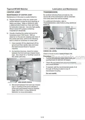
Center Joint
Converting
Drive Shaft Spline Lubrication, Middle And Rear
Emergency Exits, Check Monthly
Engine Serpentine Belt, Replacing
Filters
Fire Prevention
Hydraulic Oils
New Machine Maintenance
Oil Lost From Leakage
Pressurized Water System Maintenance
Relief Valve Adjusting Procedure
Replacing The Engine Serpentine Belt
Scheduled Maintenance
Service And Lubrication Chart
Speed Control Lever Adjustment
Startup Procedure After Maintenance
Torque Chart
Torque Chart, General
Transmission
Wheels, Installing
-PILOT SYSTEM
Accumulator Charge Valve
Accumulators
Components
Hydraulic Oil Heating Procedure
Pilot Circuit Description
Pilot Circuit Diagram
Pilot Manifold
Pilot Pressure Settings
Release Pilot System Pressure
-ELECTRICAL, GAUGES & ALARMS
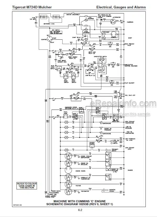
Electrical Schematic
Gauges And Alarms
Instrument Panel Wiring Diagram
Relays And Fuses
Sensor, Sender Locations
Start And Fuel Solenoids
Testing Gauges
Wire Colour Code Chart
-ENGINE
Circuit Description
Cooling System
Parking Brake
Precleaner
Relays, Diodes And Fuses Panel
Start And Fuel Solenoids
Start Circuit Diagrams – Cummins ‘c Engine
Starting System Description
Tachometer Set-Up
-DRIVE
Axles
Circuit Diagram, Drive
Drive Limiter Control Valve
Drive Pedal Pilot Valve
Drive Prevent Valve
Drive Shaft, Front, Installation
Hydrostatic Drive Motor
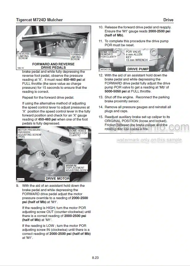
Hydrostatic Drive Pump
Hydrostatic Drive System
Pressure Settings And Adjustments
Test Drive
Transmission 1-Speed (Dual Motor)
Transmission 2-Speed (Single Motor)
Wheel Installation
-BRAKES AND DIFFERENTIAL LOCKS
Auxiliary Set-Up Caliper
Brakes
Differential Locks
Parking Brake
-OIL COOLER/RADIATOR AND CROSS-FLOW FAN
Check Maximum Fan Speed Forward And Reverse
Circuit Diagram, Cross-Flow Fan
Circuit Diagram, Oil Cooler
Cooling System, Engine See Section 7 In This Manual
Cross-Flow Fan Circuit Diagram
Cross-Flow Fan With Electronic Fan Drive Control
Electronic Fan Drive Control (FDC)
Engine Cooling System See Section 7 In This Manual
Fan Cooling Circuit Description
Fan Drive Motor
Fan Drive Motor Installation
Fan Drive Pump
Fan Drive Pump Pressure, Check
Fan Pump Forward And Reverse Max. Displacement Set
Fan Speed, Max. Forward And Reverse
FDC Control
Hydraulic Oil Tank
Oil Cooler
Oil Cooler And Radiator Installation
Oil Cooler Circuit Description
Oil Cooler Circuit Diagram
Trouble-Shooting Guide
-STEERING AND CENTER JOINT
Center Joint
Circuit Description
Circuit Diagram
Joystick Control Valve
Pressure Settings
Safety
Steer Relief Valve
Steer Valve
Steer/Boom Pump
-LIFT BOOM
Boom Lift Lock
Boom Valve
Circuit Diagram
Joystick Control Valve
Pressure Settings
Pump, Description
Safety
-TILT
Boom Lift Lock
Circuit Description
Circuit Diagram
Control Valves
Pressure Settings
Safety
-ATTACHMENT DRIVE
Attachment Motor See Attachment Manufacturer’s Manual
Attachment Pump
Circuit Description
Circuit Diagram
Control Valve, Cutter
Pressure Settings
Safety
-CLAMPS WITH SAW ATTACHMENT
Boom Lift Lock
Boom Valve
Circuit Description
Circuit Diagram
Control Valves
Pilot Line Pressures See Section 5 – Pilot System
Pressure Settings
Relief Valves
Safety
Spool Section Diagram
-MULCH DEFLECTOR DOOR
Boom Lift Lock
Boom Valve
Circuit Description
Circuit Diagram
Control Valves
Pilot Line Pressures See Section 5 – Pilot System
Pressure Settings
Safety
Spool Section Diagram
What you get
You will receive PDF file with high-quality manual on your email immediately after the payment.




Reviews
There are no reviews yet