


Factory Repair Manual For Toyota Forklift. Manual Contains Illustrations, Instructions, Diagrams For Step By Step Remove And Install, Assembly And Disassembly, Service, Inspection, Repair, Troubleshooting, Tune-Ups.
Format: PDF
Language: English
Pages: 428
Number: CE 340-1
Searchable
Wiring Diagrams
Hydraulic Diagrams
Model
Toyota Forklift
7FBEST10
7FBEST13
7FBEST15
Contents
-GENERAL
Vehicle Exterior View
Vehicle Models
Frame Number
How To Use This Manual
Explanation Method
Disassembly – Inspection – Reassembly
Terminology
Abbreviations
SI Units
Operating Tips
General Instructions
Jack-Up Point
Lifting The Vehicle
Member Weights
Towing The Vehicle
Electrical Parts Inspection
Notes On SAS
Tightening Torque Table
Recommended Lubricant Quantity And Types
Periodic Maintenance Table
Lubrification Chart
-BATTERY
Battery Compartment And Required Weight
Service Standards
Display
Battery Charge Indicator
Vehicle Behaviour With Discharged Battery
Vehicle Behaviour With Overdischarged Battery
Troubleshooting
Battery
Inspection
-CONTROLLER
General
Specifications
Components
Before Repair
Inspection
Connector Inspection
Traction Logic Unit
Pump Logic Unit
I/O Control Board
SAS Control Board
Minilever Mhyrio Board
Armrest Board
Controller
Traction & Pump Logic Unit
Operational Feature
Diagnosis
General Precautions
Protections
Minilever I/O Control Board (Mhyrio)
Armrest Board
I/O Control Board
Contactor Panel
Check Traction Motor Phases Balancing
Check Pump Motor Phases Balancing Measuring Method Procedure
Conctactor Panel Assembly Drawing
Display
Direction Switch
Accelerator Potentiometer Adjustment
Brake Switch Adjustment
-MULTI-DISPLAY FUNCTIONS
Multiple Display
General
Display And Buttons
Customer S Accessible Function
Turtle Function
P Special- Program Activation
P Special- Program Disabling
Mask Functions
Preparation For The Mask Menu Screen
Mask Function List
Password
Password Input Procedure
Operating Procedure
Category Modification
Classes Modification
Analyzer
Active Test
Tuning
Option
Matching
Alarms
-TROUBLESHOOTING
Before Troubleshooting
Connector Handling
Wire Harness And Connector Inspection Procedure
System Configuration With Mechanic Control Valve
System Configuration With Electric Control Valve
Diagnosis Code List
When An Error Code Is Displayed
Traction Logic Unit
Pump Logic Unit
Minilever I/O Control Board (Mhyrio)
SAS Control Board
Armrest Board
Dashboard
I/O Control Board
-MOTOR
Drive Motor
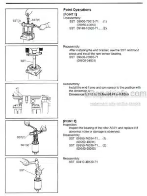
Point Operations
Pump Motor
Point Operation
-REAR AXLE
Rear Axle
Components
Steering Hydraulic Motor
Steering Potentiometer
Steering System
Hydraulic Motor
Steering Potentiometer
Rear Axle & Drive Unit
-STEERING
Power Steering System
Components
Hydrostatic Steering Valve
Troubleshooting
Power Steering
Point Operations
Inspect And Adjust The Relief Pressure
Priority Valve
-BRAKE
Brake System
Parking Brake
Brake Pedal
Front Brake
Brake Group
Brake Shoes And Brake Cylinder
Point Operations
Brake Pedal
Brake Pedal Adjustment
Parking Brake
Point Operations
Parking Brake Adjustments
Adjustment
-BODY & FRAME
Components
Body & Frame
Battery Cover
Counterweight
Operator’S Seat
Fuses
Fuse Installation Locations
Names (Applicable Functions) And Capacities
-MATERIAL HANDLING SYSTEM
Hydraulic Circuit (Mechanic Control Valve)
Hydraulic Circuit (Electric Control Valve)
Components
Steering System
Hydraulic System (With Mechanic Control Valve)
Hydraulic System (With Electric Control Valve)
V Mast
FV Mast
FSV Mast
Hydraulic Oil And Filter
Point Operations
Natural Drop Test On Lifting
Natural Forward Tilting Test
Oil Leak Test
Lifting Cylinders
Tilting Cylinders
-MAST
V Mast
Components
Mast (V)
Fork Carriage
Chain And Chain Wheel
Point Operations
T And Fork Carriage Rollers (All Mast Types)
Point Operations
Mast And Fork Carriage Rollers (All Mast Types)
Mast Chains
Fork
FV – FSV Mast
Components Mast (FV)
Fork Carriage (FV – FSV)
Chain & Chain Wheel (FV)
Chain & Chain Wheel (FSV)
-CYLINDER
Lift Cylinder
General
Specifications
Side/Rear Lifting Cylinder (V And FSV)
Central Lifting Cylinder (FV And FSV)
Side/Rear Lifting Cylinder (FV)
Components
Lift Cylinder (V)
Side/Rear Lifting Cylinder (FV)
Side/Rear Lifting Cylinder (FSV)
Central Cylinder (FV And FSV)
Side/Rear Cylinder
Central Cylinder
Flow Regulator Valve (HAWE, For All Masts)
Specifications
Mast Performance Tables
Lifting
Tilting
Tilt Cylinder
-OIL PUMP
Components
Service Pump
Test Method
Mast Performance Table (Lifting)
-OIL CONTROL VALVE
Mechanic Oil Control Valve
General
Oil Control Valve
Mechanic Oil Control Valve
With Hand Direction Lever
Mechanic Oil Control Valve
With Hand Direction Lever
Hydraulic Diagram
Specifications
Mechanic Oil Control Valve
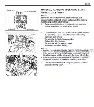
Point Operations
Maximum Pressure Valve Adjustment
Mast Performance Table
Lift Lock Unlocking Screw
Oil Control Valve Lever
Electric Oil Control Valve (For Minilever And Joysticks)
General
Oil Control Valve
Electric Oil Control Valve
Hydraulic Circuit Diagram
Specifications
Electric Oil Control Valve
Maximum Pressure Valve Adjustment
Mast Performance Table
Lift Lock Unlocking Screw
Minilever (Without And With Hand Direction Lever)
Components
Minilever (With Hand Direction Lever)
Joystick
-SAS FUNCTIONS
General
Components
For Repair Work
Steering Knob Synchronizer Valve
Tire Angle Sensor
Tilt Angle Sensor
Load Sensor
Mast Lifting Height Switch
Matching
Vehicle Standard State
Cautions On Modifying Vehicles
-APPENDIX
Load Sensor Wiring Harness
Mast Height Switch
Mast Wired Switch
Oil Control Valves Wiring Harness
Rear Window Heater Wiring Harness
Combi-Lights Wiring Harness
Rear Left Working Light Wiring Harness
Forward Working Lights Wiring Harness
Flashing Beacon Wiring Harness
Wired Buzzer 24 V
Seat Cable
I/O Control Unit
Lights Equipment Wiring Harness
3 Function Solenoid Valve Wiring Harness
4 Function Solenoid Valve Wiring Harness
Armrest Can-Bus Wiring Harness
Armrest Wiring Harness
SAS Group Wiring Harness
Wired Potentiometer
SAS Control Unit Group
Main Wiring Harness
Connectors
Ultrasonic Welding’s
Abbreviations
What you get
You will receive PDF file with high-quality manual on your email immediately after the payment.


Reviews
There are no reviews yet