Factory Service Manual For Toyota Order Picking Truck. Manual Contains Illustrations, Instructions, Diagrams For Step By Step Remove And Install, Assembly And Disassembly, Service, Inspection, Repair, Troubleshooting, Tune-Ups.
Format: PDF
Language: English
Pages: 160
Number: 216868-040 (march 2004)
Bookmarks
Searchable
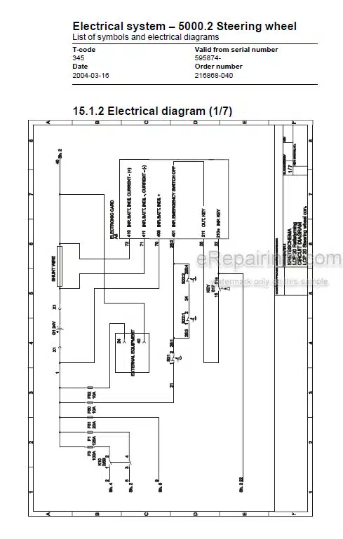
Wiring Diagrams
Hydraulic Diagrams
Model
Toyota Order Picking Truck
LOP20
Valid from serial number: 595874-
Contents
-GENERAL PRODUCT INFORMATION
General Description
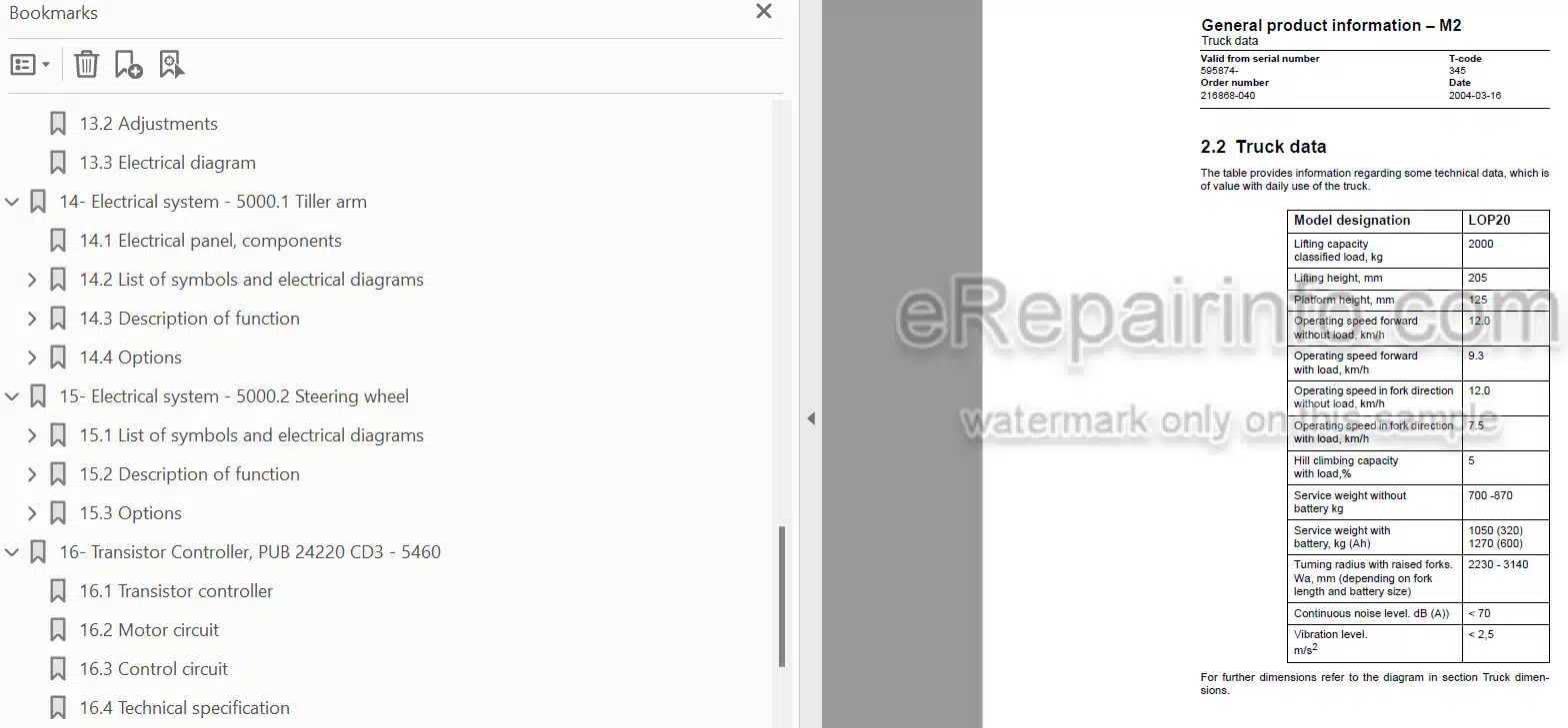
Truck Data
Truck Dimensions
Presentation Of Main Components
Controls And Instruments
TECHNICAL SERVICE DATA
-INTRODUCTION, MAINTENANCE
Safety Regulations With Maintenance Work
Cleaning And Washing
Safe Lifting
-PREVENTIVE MAINTENANCE
Maintenance Schedule
Lubrication Table For LOP20
-OIL AND GREASE SPECIFICATION
Approved Oil’S And Grease For LOP20
-FORK UNIT
General Description
Main Components Of The Fork Unit
Dismantling/Fitting The Fork Unit From/To The Chassis
Maintenance
Exchange Of Push Rods And Bush- INGS
-ELECTRIC DRIVE MOTOR
General
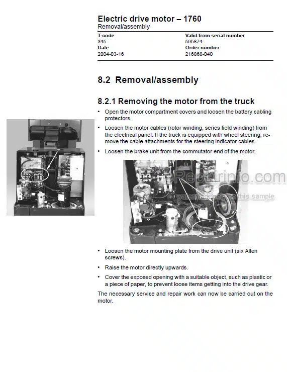
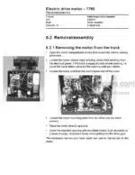
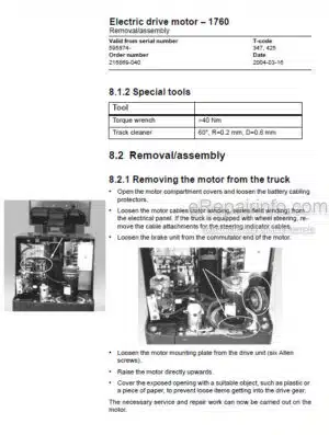
Removal/Assembly
Service/Repairs
Storage/Transport
Data
-TRANSMISSION, GEAR
General Description
Dismantling/Fitting Of Gear From/In Truck
Filling Of Oil
Exchange Of Oil
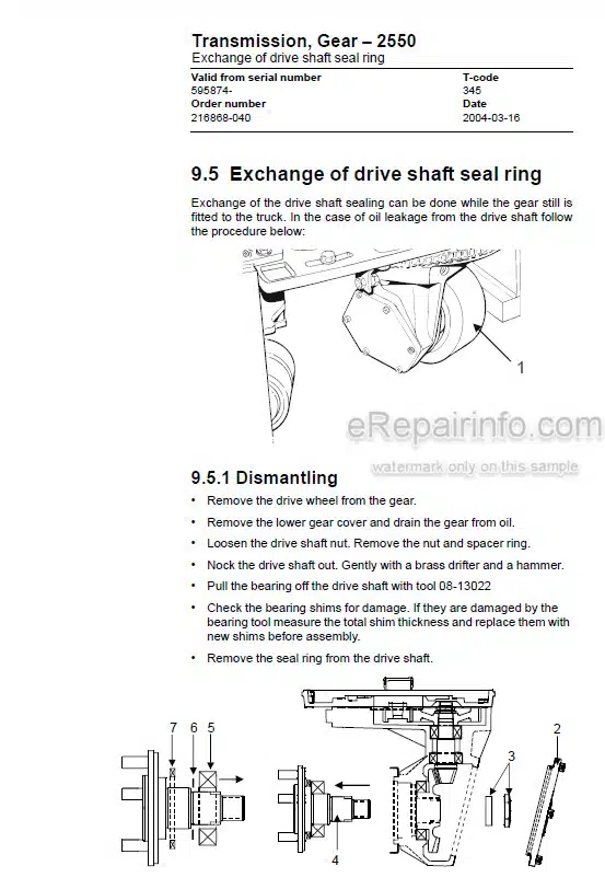
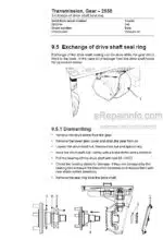
Exchange Of Drive Shaft Seal Ring
Leakage From The Top Cover
-ELECTROMAGNETIC BRAKE
General Description
Main Brake Components
Maintenance
Adjusting The Gap
Adjusting The Brake Force
Replacing The Brake Disc
-CASTOR WHEEL
General
Main Component Of Castor Wheel
Maintenance
-TILLER ARM WITH SERVO
General
Electrical Diagram
Adjustment
-ELECTRIC WHEEL/LEVER STEERING
General
Adjustments
Electrical Diagram
-ELECTRICAL SYSTEM – TILLER ARM
Electrical Panel, Components
List Of Symbols And Electrical Diagrams
Description Of Function
Options
-ELECTRICAL SYSTEM – STEERING WHEEL
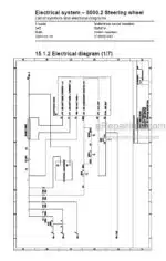
List Of Symbols And Electrical Diagrams
Description Of Function
Options
-TRANSISTOR CONTROLLER
Transistor Controller
Motor Circuit
Control Circuit
Technical Specification
LED Indications
Maintenance
Test Of Transistor Unit Safety Circuit
-LOGIC CARD – TILLER ARM
General Description
Connections And Adjustments
DIP-Switch Adjustments/Settings
Card Pin Connections And LEDs
Speed Limit
Fault/Error Indications
-LOGIC CARD – STEERING WHEEL
General Description
Basic Settings And Adjustments
Board Connections And LEDs
Speed Limit
Error Codes
Error Code Register
-HYDRAULIC SYSTEM
General
Description Of Function
-HYDRAULIC SYSTEM – WITH PLATFORM LIFT
General
Description Of Function
What you get
You will receive PDF file with high-quality manual on your email immediately after the payment.

Reviews
There are no reviews yet