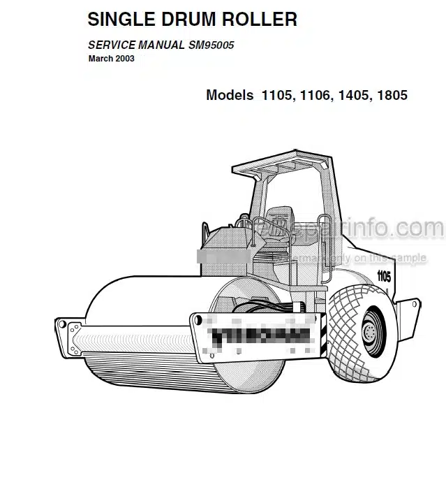
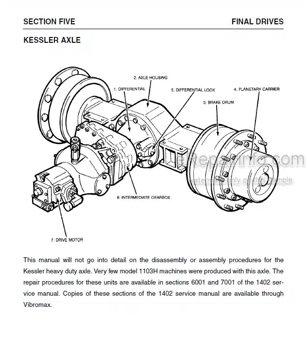
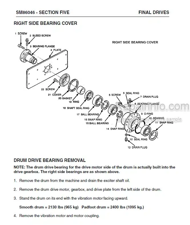
Factory Service Manual For Vibromax Single Drum Roller. Manual Contains Illustrations, Instructions, Diagrams For Step By Step Remove And Install, Assembly And Disassembly, Service, Inspection, Repair, Troubleshooting, Tune-Ups.
Format: PDF
Language: English
Pages: 240
Number: SM95005 (march 2003)
Searchable: Yes
Wiring Diagrams: Yes
Hydraulic Diagrams: Yes
Model
Vibromax Single Drum Roller
1105
1106
1405
1805
Contents
-GENERAL INFORMATION
Machine Description
Serial Numbers
Identifying Machine Components
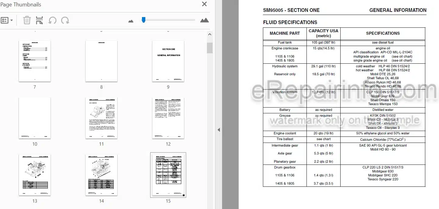
Fluid Specifications
Machine Specifications
Standard Torque Data
Diesel Fuel Specification
Engine Oil Specification
Safety General
Spark Arrester
Safety Personal
Safety Machine Operation
Safety Maintenance
Safety Decals
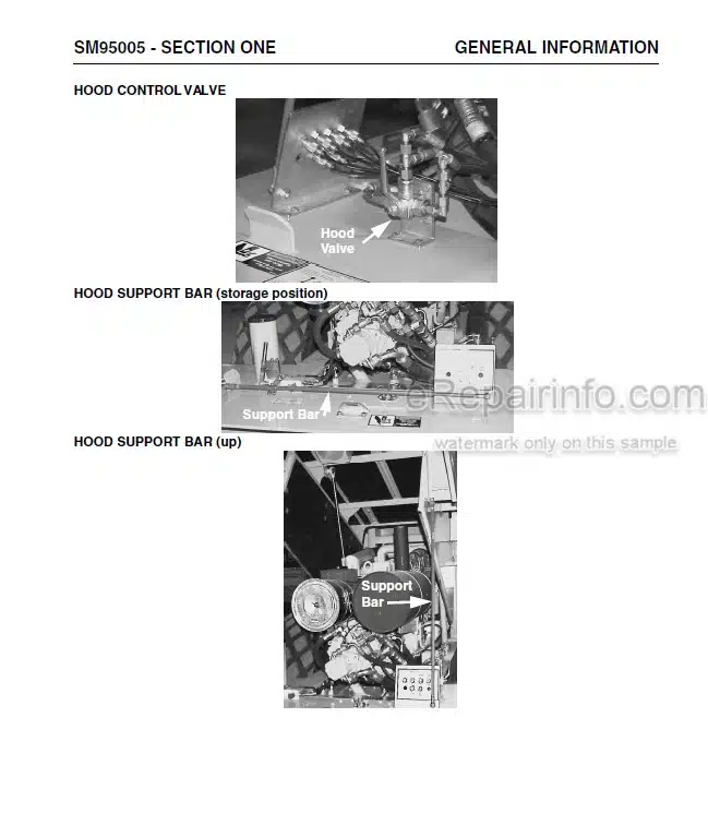
Hydraulic Hood Operation
Hood Instructions
-ENGINE
Engine Data
Cummins Engine Warranty
Engine Removal
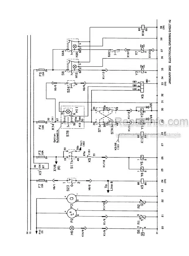
-ELECTRICAL
General Information
Fuse Location
Relay Location
Instrument Panel
Understanding Electrical Schematics
Understanding Relays
Starter/Charging Circuit (Cummins 6B59C)
Starter/Charging Circuit (Cummins 6BT59C)
Understanding Batteries
Understanding Alternators
Understanding Starters
Instrumentation Panel
Emergency Stop Switch/ Brake Switch
High Speed Circuit
Vibration Circuit
Lighting Circuit
Work Lights Accessory Plug, Heater And Wipers
Cab Wiring
Wire Harness 7241/80315 (0)
Wire Chart 7241/80315 (O)
Wire Harness 7241/80110(0)A
Wire Chart 7241/80110(0)A
Wire Harness 7241/80510(0)B
Wire Chart 7241/80510(0)B
-HYDRAULIC
Pump Suction Lines
Hydraulic Cooling System
Hydraulic Drain Lines
Hydraulic Test System
Hydraulic Test Station
Charge System
Propulsion System
Multifunction Valves
Propulsion System Diagnostics
Pump Servo Control
Vibration System
Vibration Frequency
Vibration Amplitude
Vibratory System Diagnostics
Steering System
Parking Brake System
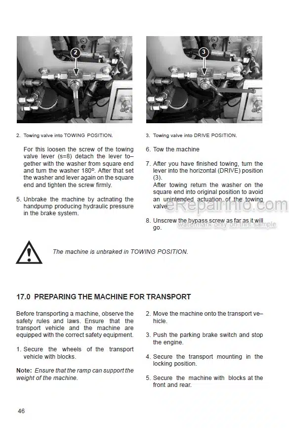
Towing Your Machine
Towing Procedure
Parking Brake Diagnostics
Differential Lock System
Hood Lift System
Hydraulic Components
Hydraulic Schematic
-POWER TRAIN
General Information
Operation
Speth Axle
Rear Axle Removal
Rear Axle Installation
Axle Tube Disassembly
Planetary Disassembly
Differential Lock Removal
Differential Lock Assembly
Axle Tube And Planetary Assembly
Intermediate Gearbox Disassembly
Intermediate Gearbox Assembly
Differential Disassembly
Differential Assembly
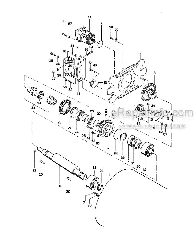
Drum Removal
Drum Installation
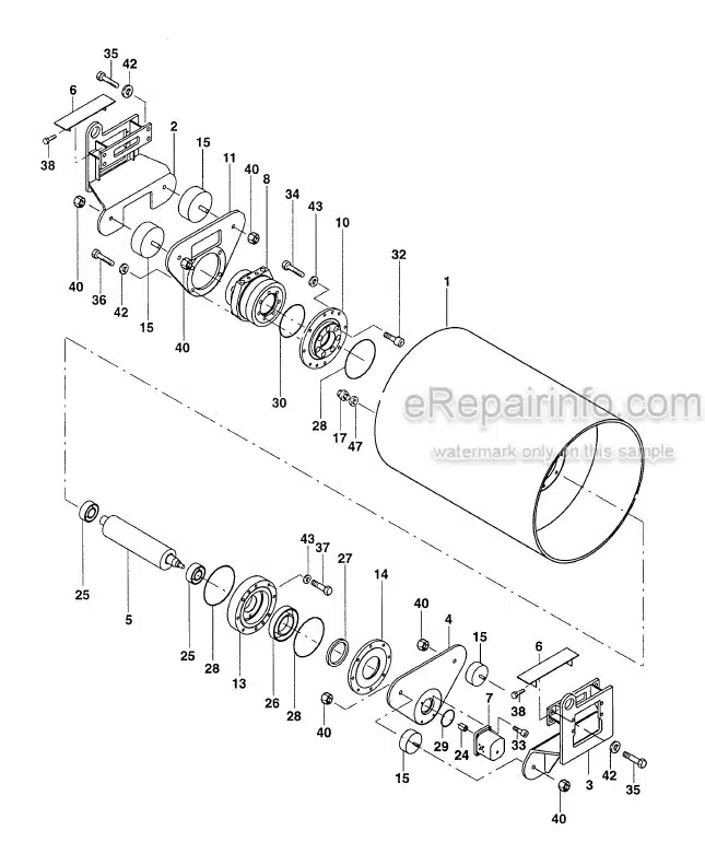
Drum Drive
Drum Drive Bearing Removal
Drum Drive Bearing Installation
Drum Drive Motor Repairs
Drum Drive Gearbox
GFT 17 T2/312 2 Gearbox
GFT 36 T3 1042 Gearbox
-PARKING BRAKE SYSTEM
Description
Brake Release And Towing
Towing Procedure
Axle Brake
-VIBRATION SYSTEM
Vibration System
Vibration Frequency
Vibration Amplitude
Vibratory System Diagnostics
Lifting Device
Drum Removal
Drum Installation
Exciter Bearing Removal
Exciter Bearing Assembly
Drum Exciter Shaft
-STEERING SYSTEM
Special Tools
Articulation Joints
Joint Disassembly
Joint Assembly
Steering Cylinder
-CHASSIS
Drum Frame
Rear Frame
Hood
Operator Platform
Rollover Protection Structure
-ATTACHMENTS
Leveling Blade
Blade Control
Blade Hydraulic Lines
What you get
You will receive PDF file with high-quality manual on your email immediately after the payment.

Reviews
There are no reviews yet