Factory Service Repair Manual For New Holland TT60, TT75A Tractors. Tons of illustrations, instructions, diagrams for step by step remove and install, assembly and disassembly, service, inspection, repair, troubleshooting, tune-ups.
Format: PDF
Language: English
Pages: 708
Bookmarks: Yes
Searchable: Yes
Number: 84154805
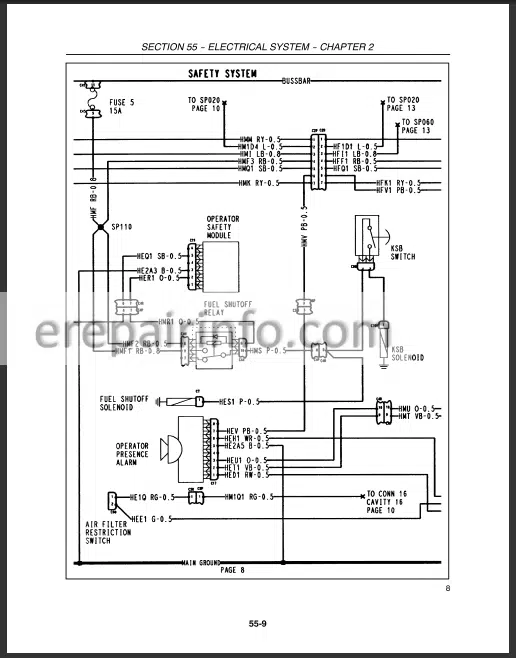
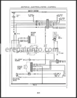
Wiring Diagrams: Yes
Hydraulic Diagrams: Yes
Model
New Holland TT60A, TT75A
Contents
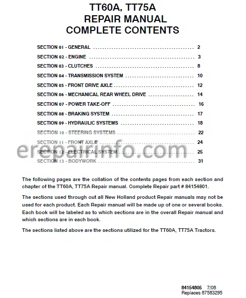
- General
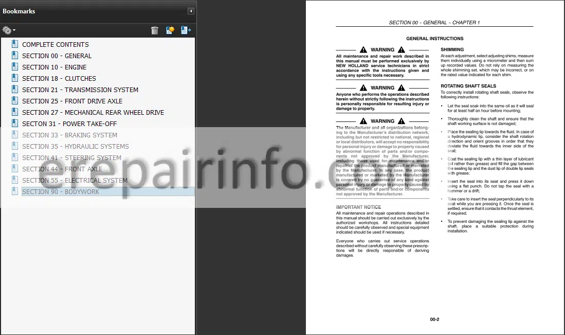
General Instructions
Important Notice
Shimming
Rotating Shaft Seals
Orings
Sealers
Bearings
Spring Pins
Precautionary Notice
Equipment Notice
Spare Parts Notice
General Notices
Health And Safety
Health And Safety Precautions
General Workshop Toots And Equipment
Legal Aspects
Lubricants And Greases
Precautionary Statements
Safety
The Tractor
Driving The Tractor
Operating The Tractor
Operating The Pto
Servicing The Tractor
Diesel Fuel
Ecology And The Environment
Minimum Hardware Tightening Torques
General Dimensions
Federal Emissions Warranty
California Emission Control Warranty Statement
Universal Symbols
Safety Decals
Safety Decals
Instructional Decals - Engine
Engine Torque Specifications
Metric Beit Torque Specifications
Special Toots
Troubleshooting
Description arid OperabonEngine Components
Cylinder Head assembly
Camshaft Assembly
Cylinder Bloch Assembly
Crankshaft Assembly
Connecting Rode
Pistons
Manifolds
Timing Gears
Lubrication System
Cooling System
Fuel System
Fuel Shut Off (injection Pump)
tuft Pimp
Fuel Filters
Engine Preparation
Engine RemovalInstallation
Separating Engine from Transmission Hous>ng
Separating Front Axle from Engine
Engine Installation
Engine Compression Test
Test Procedure
test readings
Test Condition
Cylinder Head
Roper And Inspection
Injector Sleeves
Valve Settings
Valves
Valve Guides
Valve Springs
Tappets And Pushrods
Rocker Shall
Front Engine Caver
Timing Gear
Idler Gear
Fuel Pump Drive Gear
Fuel Iroction Pump Drive Gear
Camshaft Drive Gear
Hydraulic And Power Steering Pump Drive Gear
Inspection And Repair
Camshaft
Camshaft Drive Gear
Camshaft Bearings
Idler Gear Bushing
Camshaft Fuel Pump Drive Gear, Hydraulic And
Power Steering Dnvo Goals
Front Seal
Valve Timing
Adjustment
Oi Pan
Dynamo Balancer
Connecting Rods Bearings, Reasons And Rngs
Connecting Rod Alignment
Cylinder Block
Flywheel
Man Bannng And Crankshaft
Fuel System
Ar Cleaner
Service The Engine Air Cleaner Outer Element
Fuel Injection Pump
The Fuel injection Pump Tlmog With Pump On The Tractor
Fuel System Air Bleeding
Injector
Testing And Overhaul
Fuel Pump
Lubrication System
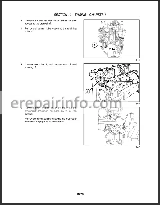
Oil Pump
Oil Filter
Oil Pressure Warning System
Engine Oil Consumption Diagnosing Procedure
Oil Consumption Test Procedure
Compression Test
Teet Heatings
Test Conclusion
Rework Instructions
Oil Consumption Tost Form
Cooling System Iis
Radiator
Removal
Report And Inspection
Thermostat
Water Pump
Water Temperature Gauge
Belt Tension Adjustment - Clutches
Clutch assembly
Cutch Plate
Longitudinal Section
Clutch Mechanical Release Control
Clutch Pedal
Pto Clutch Lever
Cross Shafts
Transmission Pto Release Bearing Assembly
Transmission Clutch Pedal FreeTravel And Adjustment
Adjusting Pto Clutch Linkage
Clutch Assembly
Release Fingers
Release Lever Height Adjustment
Important Points To Be Taken Into Account While Replacing Clutch - Transmission System
Precaution At Flange And Tool Ends
Reassembling Methods
Recommendations Regarding Lubrication
Shaft Seals
ORing
Adjusting Shims
Bearings
Sealing
Oil Drain
Sealants
Special Tools
Description And Operation
Transmission Internal Components
Drive Shaft Removal
Drive Shaft Installation
EndPlay Specification
Gear Rails
Special Tool Required
Range Gear (EpiCyclic) Assembly
Reverse Gears And Drive Shaft
Driven Gears And Drive Shaft
Checking Driven Gear Shaft Endplay
External Components Gear Shift Lever
Reverse Lever And Cover - Front Drive Axle
Front To Rear Axle Ratio
Front Axle
Steering Knuckle Pms And Bearings
Stub Axle Adjustment
Wheel Hub Bearing Adjustment
Bevel Drive Adjustments
Adjustment Of The Preload Of The Pinion Shaft Bearings
Determining The Thickness Of The Drive Pinion
Position Adjustment Shim
Ring/Pinion Adjustments
Adjustment Of The Ring Gear Bearings And Checking The
Backlash Between The Pinion And Ring Gear
Front Axle Differential
End Float Adjustment
Toe In Adjustment - Mechanical Rear Wheel Drive
Description And OperationMechanical Rear Wheel Drives
Differential Lock
Rear Wheel Drive Housing
Differential Unit
Pinion Shaft
Shift Rails
Adjustments And Settings
Bevel Drive Shaft Bearing Preload Adjustment
Bevel Pinion Shaft Depth Adjustment
Assembling The Bevel And Pinion Shaft
Differential Bearing Adjustment And Bevel Drive Backlash Check
Differential Pinion And Side Gear Backlash Adjustment
Adjustment Of Ring Gear Bearings - Power TakeOff
Sealants
Sectional View
Description And Operation
Power TakeOff
Adjustments
Pto Clutch
Pto Shaft Assembly
Pto Brake - Braking System
Metric Boll Torque Specifications
Sectional Views Brake Control Assembly
Description And Operation Brake System
Brake Pedals And External Linkages
Parking Brake Linkage
Brake Pedal Free Play Adjustment - Hydraulic Systems
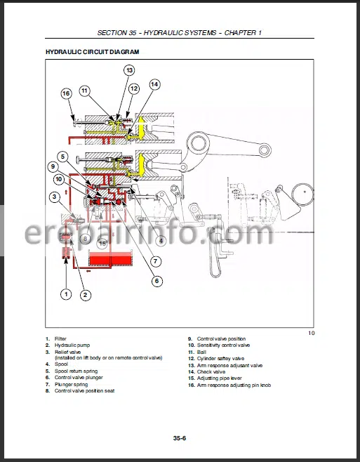
Introduction And Circuit Identification
Pump
Filter
Mechanical Hydraulic Lift Assembly
Remote Control Valve
Open Center Hydraulic Circuit And Mechanical Lift
Schematic View Of Hydraulic System
Hydraulic Circuit Diagram - Steering System
Steering Pump
Steering Test
Steering Retief Valve Pressure Test
Relief Valve AdjustmentAll Models
Description And Operation
Operation
StraightAhead Driving
Rh Steer
Lh Steer
Emergency Hydraulic Steer (C Sed Ses)
Power Cylinder Safety And Make Up Valves (N)
Hydrostatic Steering Reservoir
Inspection And Cleaning
Steering Motor
Inspection And Replacement
Lubrication
Assembly Pattern For Standard Bearing
Installation Of ORing
Installation Of Lip Seal - Front Axle
Front Axle Support
Stub Assembly
Troubleshooting
Description And Operation
Front Axle Assembly
Front Wheel Hub
Spindle Assembly
Front Wheel Setting Tests
Wheel Camber Test
Front Wheel ToeIn Test - Electrical System
Description Of Electrical System
Component Location And Function
Wiring Harnesses
Grounds
Battery And Fuses
Battery
Description
Checking The Battery Electrolyte Level
Fuse Block
Fuse Replacement
Fuse Identification
Fusible Link
Electrical System Components — Description And Testing
Key Switch
Key Switch Terminals
Testing
Light Switch
Description
Terminal Identification
Light Switch
Testing
Hazard Light Switch
Turn Signal Switch
Transmission Range Safety Switch
Pto Safety Switch
Park Brake Safety Switch
Seat Safety Switch
Transmission Clutch Safety Switch
Relays
Description And Location
Testing (Neutral Start)
Testing Micro Relays (Fuel Shutoff, Pto Safety Stan
Hazard Flasher Cutoff)
Hazard FlasherTurn Signal Control Module
Operator Safety Module
Description And Location
Park Brake Safety Alarm (Buzzer)
Engine Sensors
Engine Oil Pressure Sender
Engine Coolant Temperature Sender
Ksb Temperature Switch
Ax Filter Restriction Switch
Fuel Level Sender
Lighting
Head Lamp
Bulb Replacement
Turn/Position Lights/Flasher
Bulb Sizes - Bodywork
Engine Hood Panel Assembly
Rear Wheel Fenders
Roll Over Protection (Rops) Bar
Battery
What you get
You will receive PDF file with high-quality manual on your email immediately after the payment.

Reviews
There are no reviews yet