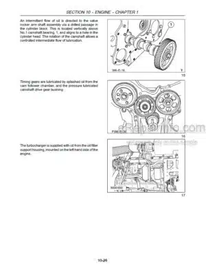
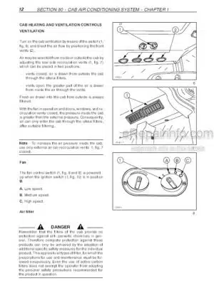
Factory Service Manual For New Holland Grape Harvester. Manual Contains Illustrations, Instructions, Diagrams For Step By Step Remove And Install, Assembly And Disassembly, Service, Inspection, Repair, Troubleshooting, Tune-Ups.
Format: PDF
Language: English
Pages: 543
Number: 6048233100
Bookmarks: Yes
Searchable: Yes
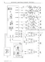
Wiring Diagrams: Yes
Hydraulic Diagrams: Yes
Model
New Holland Grape Harvester
VL570
VL600
VL610
VL620
VL630
VL640
VL660
VM370
VM460
VN300
Contents
-SPECIFICATIONS
Machine Identification
Dimensions
Self Propelled Machine Technical Specifications – VL 600; VL 660 And VM 460
Harvesting Equipment Technical Specifications VL 600 – VL 660 And VM 460
Self Propelled Machine Technical Specifications – VL 570 VM 370 And VM 300
Harvesting Equipment Technical Specifications VL 570 VM 370 And VM 300
-MAINTENANCE
Capacities
Thermal Engine Maintenance
Greasing
Hydraulic Filter
Washing
Hydraulic System Maintenance
Routine Maintenance And Winter Storage
-MACHINE PREPARATION AND EQUIPMENT
Console Adjustment .
-ENGINE
General Specifications
Main Data And Injector Calibration
Tightening Torques
Tools
Engine Views
Lubrication Diagram
Cooling Diagram
Fault Diagnosis
Engine Compression Test
Engine Checks, Measurements And Repairs
Crankshaft Front Seal – Replacement
Crankshaft Rear Seal – Replacement
Valve Tappet And Rocker Arm Clearance – Adjustment
Engine Injector R.I.
Bosch Injection Pump R.I. Timing Air Bleed
Coolant Pump R.I.
Thermostat Valve R.I.
Coolant Pump And Generator Drive Belt Tension Adjustment
-LIVE PTO
-HYDROSTATIC TRANSMISSION
Component Location
Transmission Diagram And Operation
Traction Reduction And Steering Valve
Hydrostatic Pump
HP Hydraulic Block
Braking Hydraulic Block
Capacity Distribution Block (Optional VN300)
Hydrostatic Motors
Range And Speed Technical Specifications
First Start -Up
-BRAKES & CONTROLS
Rear Brake Check And Repair
-HYDRAULIC SYSTEMS
Position Of Components
Intake And Return Diagram – From VL600 And 660 To VM460
Intake And Return Diagram – VL570 VM370 And VN300
Cleaning Hydraulic Circuit – From VL600 And 660 To VM460
Cleaning Pump Control Hydraulic Block – From VL600 And 660 To VM460
Cleaning Hydraulic Pump And First Starting – From VL600 And 660 To VM460
Cleaning Hydraulic Block – From VL600 And 660 To VM460
Cleaning Hydraulic Circuit VL570 VM370And VN300
Cleaning Pump Control Hydraulic Block – VL570 VM370 And VN300
Cleaning Hydraulic Block VL570 VM370 And VN300
Shaking Hydraulic Circuit Up To Series
Shaking Hydraulic Block Up To Series
Shaking Hydraulic Circuit Starting From Series
Shaking Hydraulic Circuit Starting From Series
Lifting Hopper And Cooling Hydraulic Circuit From VL600 And 660 To VM460 Lifting Hopper And Cooling Hydraulic Circuit VL570 VM370 And VN300
Lifting Hydraulic Block
Steering Hydraulic Circuit – From VL600 And 660 To VM460
Steering Hydraulic Circuit VL570 VM370 And VN300
Component Cutaway View
Pressure And Speed Specifications
-FRAMES
Front Leg VL600 – 660 And VM460
Rear Wheel Link VL600 + 660 And VM460
Front Leg VL570. VM370 And VN300
Rear Wheel Link VL570 VM370 And VN300
-STEERING
Steering Relays
Steering Lock Adjustment
-WHEELS
Introduction
Tyre Type
Wheel Tightening Torque
Inflation Table
-CAB CLIMATE CONTROL
Safety Precautions
Specifications
Wiring Diagram
-ELECTRICAL SYSTEMS
Component Management And Welding
Steering Aids
Control Panel
Constant Setting And Values
Component Description.
Electrical Cable Description
Electrical Connection Description
Electrical Connection Location And Ground Points
Fuse Location
Detail Of Cable Harness And Electrical Connections
Panel Card Connections And Electronic Version
Card P Programming
Electrical Inching Control
Operated Solenoid Valve EV Status
Shaking Gauge And Sloping Indicator Control Unit
Sensors And Probes
Motors And Speed Settings
-ATTACHMENTS/HEADERS
Operation
-PRODUCT FEEDING
Rails And Slides
-CLEANING
Upper Extractors
Lower Extractors
Lower Stalk Choppers
-GRAPE STORAGE – HOPPERS
Harvested Crop Distribution Auger VL600 – 660 And VM460
Harvested Crop Distribution Auger Vl570 VM 370 And VN300
-ACCESSORIES
Equipment
Multipurpose Variants
Multipurpose Table
Equipment Description
Link
Ballast Holding Arch Cable Harness
Destemmers
Sloping And Height Automatic Correction (CDHA)
Shaking Reduction On Cement Stakes (RSPB)
-PLATFORM, CAB, BODYWORK AND DECALS
What you get
You will receive PDF file with high-quality manual on your email immediately after the payment.




Reviews
There are no reviews yet