Factory Service Training For Bomag Road Finisher. The Bomag Service Training Manual Describes The Disassembly, Dismantling, Assembly, Installation And Repair Of Components And Assemblies. Manual Addresses The Professionally Qualified Personnel Or The After Sales Service Of Bomag, And Should Be Of Help And Assistance In Correct And Efficient Repair And Maintenance Work.
Format: PDF
Language: English
Pages: 1050
Number: 00892207 (february 2013)
Bookmarks: Yes
Searchable: Yes
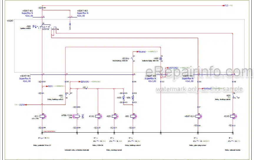
Wiring Diagram: Yes
Hydraulic Diagram: Yes
Model
Bomag Road Finisher
BF300C
S/N 821 837 57 1001 ….
S/N 821 837 69 1001 ….
S/N 821 837 82 1001 ….
S/N 821 891 03 1001 ….
S/N 821 891 04 1001 ….
Contents
-GENERAL
Introduction
Safety Regulations
General Repair Instructions
Tightening Torques
-TECHNICAL DATA
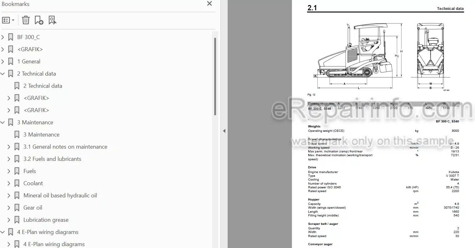
Technical Data
-MAINTENANCE
General Notes On Maintenance
Fuels And Lubricants
Table Of Fuels And Lubricants
Running-In Instructions
Maintenance Table
-E-PLAN WIRING DIAGRAMS
Understanding E-Plan Circuit Diagrams
Circuit Symbols In E-Plan
Identification Of Switch Blocks In The Wiring Diagram
Designation Of Components In The Wiring Diagram
Terminal Designations In Wiring Diagram
-ELECTRICS
Ecomode
Glow Plugs, R81-R84
Speed Sensors, B191 And B192
Oil Pressure Switch (B06)
Coolant Temperature Switch (B53)
Air Filter Vacuum Switch (B03)
Coolant Float Switch (B55)
Charge Control Light
Glow Plugs
Water Separator In Fuel Filter (B124))
Level Sensor In Diesel Tank (R03)
Fuses
Fuse Assignment
Component Overview
Overview Of Wiring Looms
Control Elements
View Of Operator’s Stand
Monitoring Modules
View Of Outside Control Stand
View Of Screed Control
View Of Electric Heating Control Panel
Functional Block Diagram Overview Of Functions, Complete
Block Diagram Components On CAN
Block Diagram Can With Control Elements
Block Diagram Of Travel Circuit
Block Diagram Material Feed
Block Diagram Screed
Block Diagram Screed Levelling
Block Diagram Screed Heating
Functional Block Diagram Monitoring Functions
Block Diagram Emergency Stop Functions
Checking The Voltage Supply For The Control Unit
Diagnostics Concept
-INPUT CODES
Input Codes – Display: Functions And Operation
Automatic Calibration Of Travel System Currents
Automatic Calibration Of Travel System Currents
Teaching The E-Throttle Function
Teaching The L.C.S. Function
Travel Signal By Button For Max. Screed Relief
Resetting To Factory Settings
Showing Stored Faults
Showing Saved Faults With Operating Hours
Deleting The Fault Log
Driving Against The Closed Brake
Adapting The Engine Speed
Deactivating/Activating Automatic Speed Range Change When Cornering
Deactivating / Activating The Speed Sensor(S)
-REPLACEMENT OF COMPONENTS
How To Proceed When Replacing Components
-ENGINE
Features
Cooling System
Removing And Installing The Thermostat
Checking The Thermostat In Disassembled State
Check The Coolant Level
Check The Anti-Freeze Concentration And The Condition Of The Coolant
Change The Coolant
Checking Radiator Hoses And Hose Clamps
Clean The Cooling Fins On Engine And Hydraulic Oil Cooler
Checking The Engine Oil Level
Changing Engine Oil And Oil Filter Cartridge
Fuel System
Replace The Fuel Filter
Checking, Cleaning The Water Separator
Changing The Fuel Filter, Bleeding The Fuel System
Check Fuel Lines And Clamps
Check The Fuel Injection Nozzles
Check The Fuel Injection Timing
Check The Fuel Injection Pump
Servicing The Generator V-Belt
Air Filter Maintenance
Check The Engine Mounts
Engine Conservation
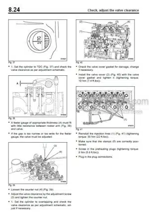
Check, Adjust The Valve Clearance
Engine Problems
-MATERIAL HOPPER, DESCRIPTION
Material Hopper And Transport
-VIBRATING SCREED, DESCRIPTION
Screed
-TRAVEL DRIVE, DESCRIPTION
Travel System
-CLEANING KIT, DESCRIPTION
Cleaning Kit
-HYDRAULICS
Hydraulic Circuit
Travel Pump, A4VG28 EP
Troubleshooting Axial Piston Pumps
Component Overview – Hydraulics
Travel Circuit
Vibration And Tamper Drive
Scraper Belt Drive
Auger Drive
Cylinder Functions
Check The Hydraulic Oil Level
Changing Hydraulic Oil And Filter
-TESTS AND ADJUSTMENTS
Special Tools, Tests And Adjustments
Checking And Adjusting The Vibration
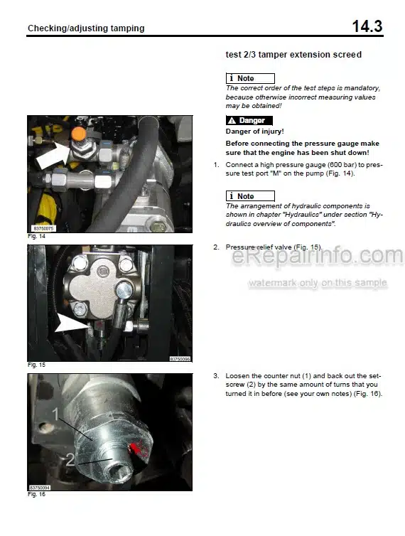
Checking/Adjusting Tamping
Checking/Adjusting The Scraper Belts
Checking/Adjusting The Augers
Checking/Adjusting The Main Screed
Checking/Adjusting The Screed Levelling
Checking/Adjusting The Hopper Wings
Checking/Adjusting The Mobile Screed
-CENTRAL LUBRICATION SYSTEM
Filling The Lubricant Container
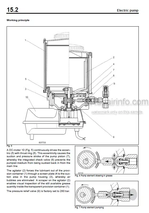
Electric Pump
Integrated Electronic Control
Progressive Distributor
Fault – Cause – Remedy
Repair Of A Blocked Distributor
-CIRCUIT DIAGRAMS
Hydraulic Diagram
Electric Circuit Diagrams
What you get
You will receive PDF file with high-quality manual on your email immediately after the payment.


Reviews
There are no reviews yet