Repair Manual For New Holland LW110 LW130 Loader. Illustrations, instructions, diagrams for step by step remove and install, assembly and disassembly, service, inspection, repair, troubleshooting, tune-up.
Format: PDF
Language: English
Pages: 334
Bookmarks: Yes
Searchable: Yes
Number: 75131007
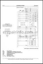
Wiring Diagrams: Yes
Hydraulic Diagrams: Yes
Model
New Holland LW110, LW130
Contents
- Home Page
Cover Page - – Summary – Contents
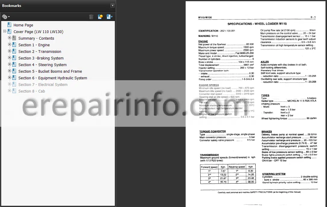
Specifications
Capacities And Fluid Types
Safety Rules
Units Of Measure
Tightening Torques - – Engine
General Description Description
General Specifications
Data – Mounting Clearance
Injection Pump Setting Data
Outer Views
Engine Supports
Main Tightening Torques And Pressure Pick-Up Points
Lubrication System
Cooling System
General Description
Radiator
Fuel System
Fuel Reservoir
Air Intake And Exhaust System
General Description
Turbo Charger
Air Cleaner
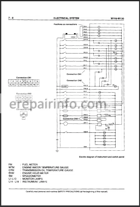
Electrical System
Batteries
Starter Switch
Starting A Cold Engine
Engine Cut-Off Device
Engine Pre-Heating Sequence
Pre-Heating Maulfunction Warning Lamp Modes
Accelerator Control Linkage - – Transmission
General Description
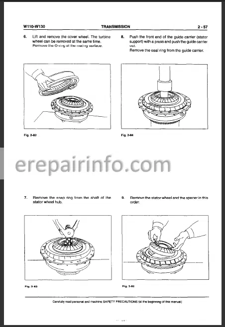
Torque Converter – Transmission
Torque Converter
Transmission – Torque Converter Pump
Transmission
Direction Clutch Shaft
Power Train Diagram
Transmision Control Valve
Transmission Control System
Configuration Of Automatic Transmission
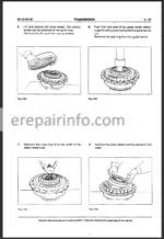
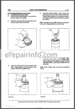
Disassembly/Reassembly Of Transmission
Disassembly
Reassembly
Troubleshooting Guide
Tightening Torque Values For Main Screws
Oil Circuit
Prop Shafts
Front And Rear Axles
Axle
Differential
Final Reduction Drive Units
Axles
Wheels
Tires - – Braking System
General Description
Operation
Operating Conditions
Disc Brank
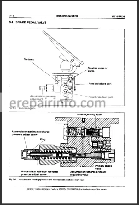
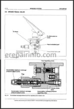
Brake Pedal Valve
Circuit Separation Valve Operation Inside The Braking System
Parking Brake Control Valve
Parking Brake
Manual Release Procedure
Disc Parking Brake Operation
Brake Disengagement
Other Components
Brake Accumulator
Checkvalve
Brake Pedal Valve Hydraulic Connections
Diagnostics And Testing
Brake Control Presure Testing Test
Minimum And Maximum Accumulator Rechange Pressure Adjustment
Parking Brake Engagement Test
Accumulator Pre-Chage Test
Accumulator Pre-Charge Reset Instructions
Bleeding The Brake System
Brake Disc Wear Check - – Steering System
General Description
Principles Of Operation Of Main Priority Valve
Steering Valve (Orbitrol)
Removal
Main Priority Valve
Secondary Priority Valve (Optional)
Cushion Valve
Steering Cylinders
Multiple Check Valve - – Bucket Booms And Frame
Load Handling System
Booms, Bellcrank And Bucket
General Description
Bucket
Bucket Automatic Leveller
Boom Kick-Out (Optional)
Frame Pivot Pins - – Equipment Hydraulic System
General Description
Oil Circuit
Equipment Hydraulic Circuit
Hydraulic System Pump
Testing And Repair Of Equipment Steering Pump
Equipment Control Valve (Mechanical)
General Description
Operation Controls
Pressure Relief Valve
Control Valve Controls
Control Valve Controls (Variant)
Hydraulic Oil Reservoir
Cylinders
Boom Cylinders
Bucket Tilting Cylinder
L.T.S. Anti-Pitching System (Variant)
Description
Dischange Of Accumulators
L.T.S. Hydraulic System Diagram
Functional Tests Of L.S.T. System
Test Of L.T.S. Accumulator Precharge
Instructions For The Re-Charging Of Accumulator
Supplementary Hydraulic Function (Variant) - – Electrical System
Safety Rules
General Lay-Out Of Electrical System
Logic Board
Connections – Relays – Timers – Buzzer
Fuses
Connectors
Cab Instrument Cluster
Indicators On Instrument Cluster
Switch Panel
Gearshift Control
Components On Machine - – Cab
General Description
Windscreen Wipers And Washers
Heater
Generalities
Main Components And Specifications
Glasses
Characteristics
Disassembly And Assembly
Repair
Cab (Removal / Installation)
What you get
You will receive PDF file with high-quality manual on your email immediately after the payment.


Reviews
There are no reviews yet