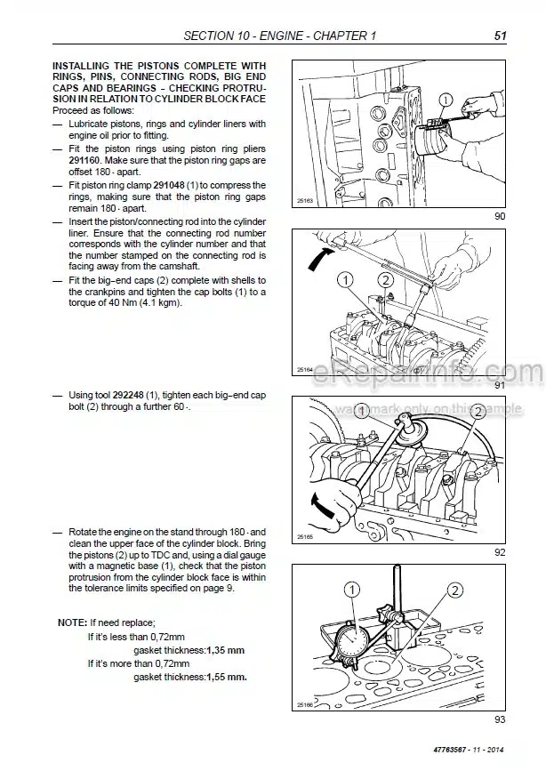
Factory Service Manual For New Holland T3.50F, T3.55F, T3.65F, T3.75F Tractor. Manual Contains Illustrations, Instructions, Diagrams For Step By Step Remove And Install, Assembly And Disassembly, Service, Inspection, Repair, Troubleshooting, Tune-Ups.
Format: PDF
Language: English
Pages: 407
Number: 47763567
Bookmarks: Yes
Searchable: Yes
Wiring Diagrams: Yes
Hydraulic Diagrams: Yes
Model
New Holland Tractor
T3.50F
T3.55F
T3.65F
T3.75F
Contents
-GENERAL GUIDELINES
General Instructions
Safety Regulations
Tractor Refuelling
-ENGINE
General specifications
Removal – Installation – Overhaul
-CLUTCH
General Specifications
Clutch – Removal – Installation
Dual Disk Clutch 11”/11” – Test Bench Overhaul
Clutch Adjustments
-TRANSMISSION-MECHANICAL TRANSMISSION
Main Data
Torque Specifications
Tools
Sections
Description And Operation
Troubleshooting
Removal-Installation -Rear Transmission Gearbox
Casing
Disassembly-Assembly -Transmission-Gearbox Casing
Disassembly-Assembly -Clutch Casing
Sealing Compound Application Diagram
Transmission Oil Cooler Removal-Installation
Power Shuttle Transmission
-DRIVE LINES
Main Data
Torque Specifications
Sections
Description And Operation
Troubleshooting
Drive Shafts And Guard Disassembly – Assembly
Removal-Installation -Drive Gear Casing
-FRONT AXLE MECHANICAL TRANSMISSION-FRONT MECHANICAL TRANSMISSION
Main Data
Torque Specifications
Tools
Sections
Removal-Installation -Front Axle
Disassembly – Assembly-Front Axle
Replacing Steering Knuckle Pins And Bearings
Adjustments – Steering Knuckle Bearings
Adjustments – Bevel Drive
Overhaul— Front Differential
Lim—Slip Self-Locking Differential
Checking Leading Wheel Alignment
Disassembly-Assembly -Front Epicyclic Final Drive
-REAR MECHANICAL TRANSMISSION
Main Data
Torque Specifications
Tools
Sections
Description And Operation
Troubleshooting
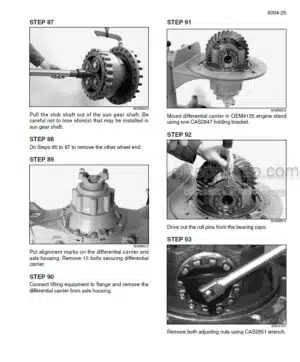
Disassembly-Assembly — Transmission-Gearbox Casing
Adjustments – Differential Lock Engagement Sleeve Position
Adjustments – Bevel Drive
Removal – Installation Side Gear Casing
Disassembly-Assembly -Drive Wheel Shaft
–POWER TAKE-OFF
Mechanical Power Take-Off
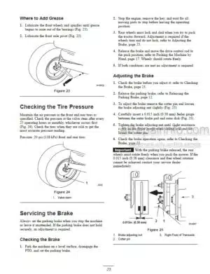
-BRAKES
Main Data
Torque Specifications
Sections
Description And Operation Troubleshooting
Removal-Installation Service Brake
Removal-Installation Service Brake Pump
Adjustments – Service Brake Pedals Travel
Service Brake Circuit Air Bleeding
-HYDRAULIC SYSTEMS
Rear Mechanical Hydraulic Lift
Open Centre System Auxiliary Control Valves
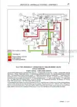
Trailer Brakes Auxiliary Control Valves
Front Loader
-STEERING
Torque Specifications
Tools
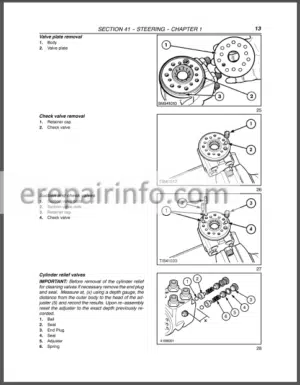
Description And Operation
View Of Hydrostatic Steering Control Valve Components
Troubleshooting
Replacement – Hydrostatic Steering Wheel
Removal-Installation Hydrostatic Steering Control Valve
Disassembly-Assembly -Hydrostatic Control Valve
Hydrostatic Steering Control Valve Bench Testing
Pressure Relief Valve Testing Steering Control Cylinder
Removal – Installation
Steering Control Cylinder
Disassembly-Assembly
-CAB AIR CONDITION SYSTEM
Safety Regulations
Main Data
Tools
Operating Principles
Conditioning System Components
Cab Controls
Testing Operation And Cooling
Air Conditioning System Maintenance
Troubleshooting
Refrigerant Recovery -Recycling And Evacuation Charging Stations
Dehydration, Recharging And Refrigeration Check
Checking For And Eliminating Any Gas Leaks
Cab Heating/Air Conditioning System Removal – Installation
Cab Electric Fan Unit Disassembly – Assembly
Air-Conditioning System Condenser Removal Installation
-ELECTRICAL SYSTEM
Instruments
Starter System
Components
Starting System
Battery
Electrical Circuits
Wiring Harnesses And Connectors
-PLATFORM, CAB, BODYWORK
Bonnet Removal Installation
Cab Assembly With Platform
Removal — Installation
Cab Right-Hand Pillar Guard Removal – Installation
Cab Right-Hand Top Guard Removal-Installation
Cab Right-Hand Mudguard Guard Removal-Installation
Cab Left-Hand Top Guard Removal-Installation
Windows Replace
What you get
You will receive PDF file with high-quality manual on your email immediately after the payment.



Reviews
There are no reviews yet